Pipeline provided with connecting components and manufacturing method thereof
A technology for connecting components and connectors, applied in the direction of pipes/pipe joints/fittings, pipes, rigid pipes, etc., can solve the problems of low production efficiency, long curing time, etc., to prevent deformation and falling apart, good economic and social benefits, The effect of improving production efficiency
- Summary
- Abstract
- Description
- Claims
- Application Information
AI Technical Summary
Problems solved by technology
Method used
Image

Examples
Embodiment 1
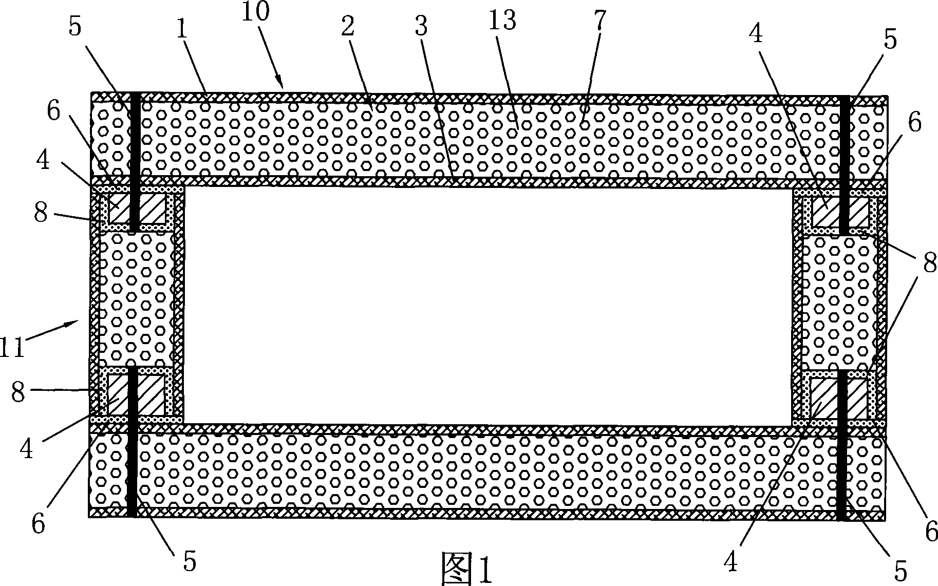
[0025]Embodiment 1: The pipeline provided with connecting components, as shown in Fig. 1, Fig. 2 and Fig. 7, is formed by splicing pipe plates. The pipe plate is a horizontal plate 10 and a vertical plate 11 with a rectangular cross section, which are composed of an outer layer 1 , a core layer 2 and an inner layer 3 . The splicing part of the vertical piping plate 11 is fixedly embedded in the connecting seat 4, the outer surface of the connecting seat 4 coincides with the splicing surface of the splicing part, and the connecting piece 5 penetrates the adjacent horizontal piping plate 10 and is inserted into the connecting seat 4 of the vertical piping plate 11 . That is to say, the connecting piece 5 is inserted into the connecting seat 4 of the adjacent piping plate through the piping plate as shown in FIG. Connecting seat 4. Figure 7 shows that the connection end of the pipe section is flat. The connection seat is a block with a large "seat nail force" (friction force, ...
Embodiment 2
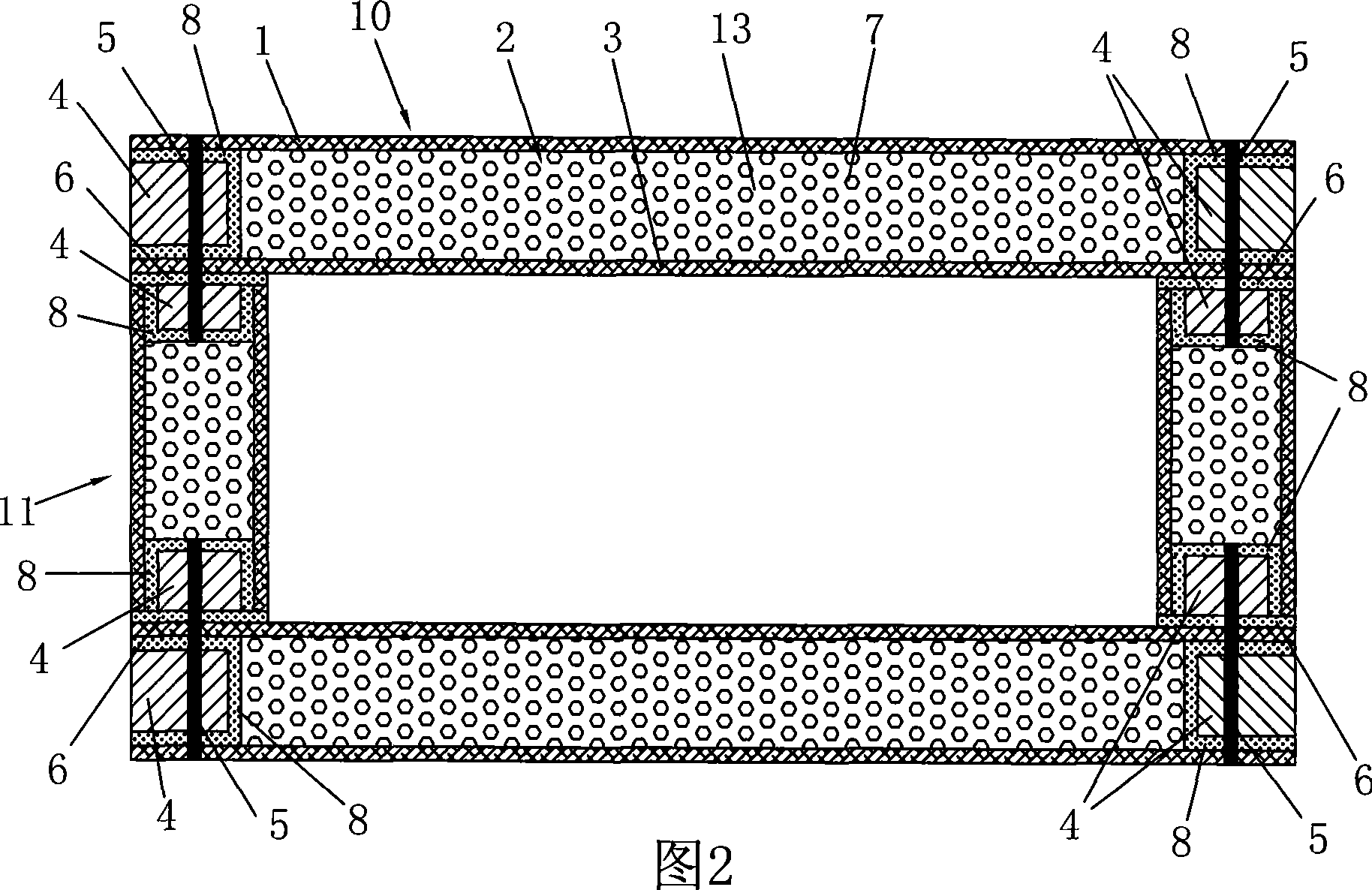
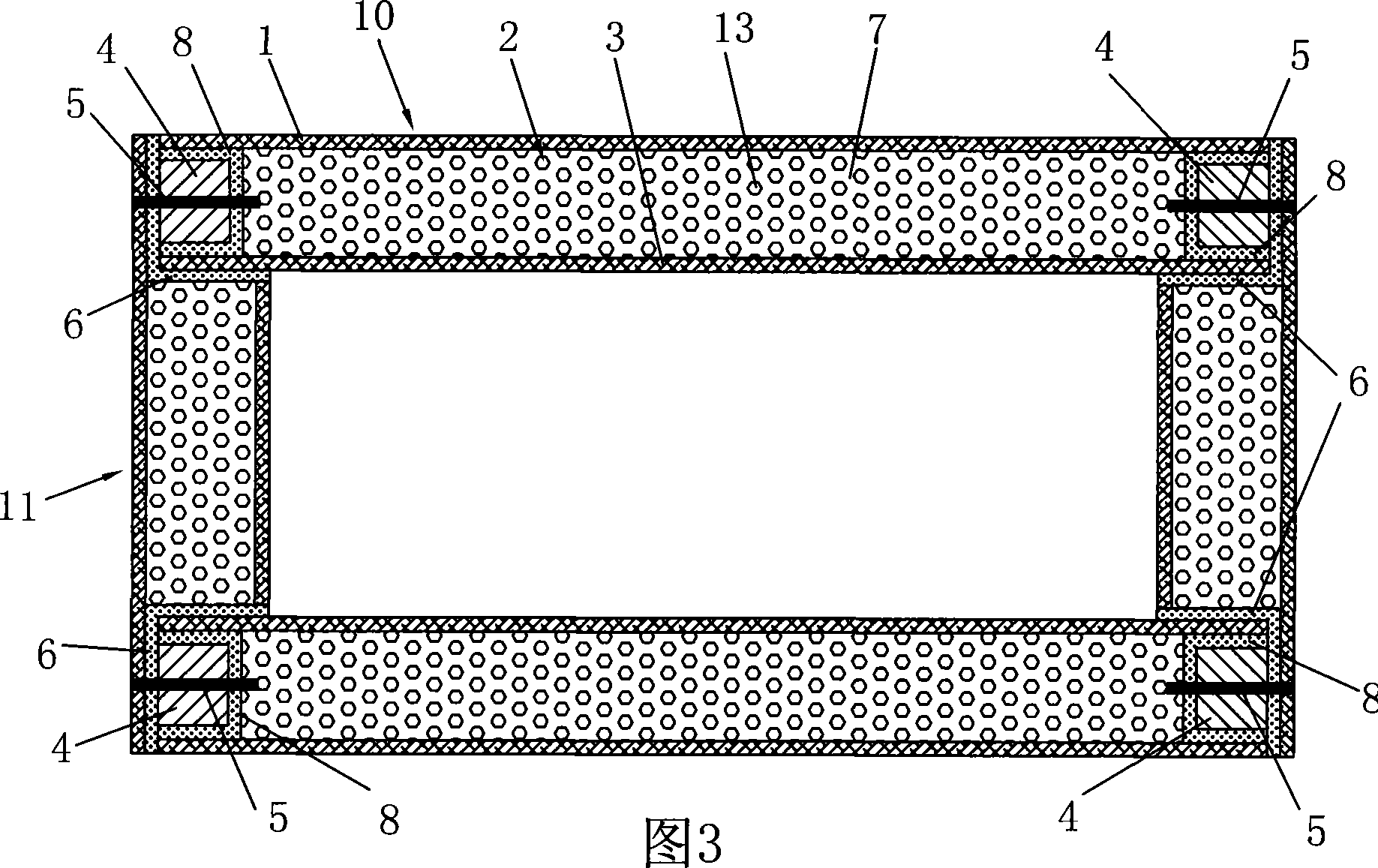
[0029] Embodiment 2: Pipelines with connecting components, as shown in Figure 3, Figure 4 and Figure 5, the splicing of the vertical pipeline plate 11 is a right-angled ladder shape equivalent to twice the thickness of the plate, and the horizontal pipeline plate 10 is a right-angled flat mouth shape, and placed in the vertical pipe plate right-angle ladder. The rest of the structure is implemented with 1. The connector 5 is inserted into the connecting seat 4 of the adjacent pipeline plate through the outer layer 1 as shown in Figure 3, or inserted into the connecting seat 4 of the adjacent pipeline plate through the pipeline plate as shown in Figure 4 (Figure 4 and Figure 1 The difference lies in the shape of the splicing part), or as shown in Figure 5, through the connecting seat 4 provided in the core layer and inserted into the connecting seat 4 of the adjacent pipeline plate (the difference between Figure 5 and Figure 2 lies in the shape of the splicing part) . In the ...
Embodiment 3
[0031] Embodiment 3: Pipes with connecting components, as shown in Figure 8, the symmetrical horizontal pipe plate 10 and the vertical pipe plate 11 are of equal length and dislocated to form a pipe section 12 with a front convex end and a rear concave end, adjacent pipes The joints are inserted through the front convex end and the rear concave end, and a connecting piece 5 is provided at the insertion position of the adjacent pipe section, and the connecting piece 5 is provided with a connecting seat 4 of the front convex end at the rear concave end. All the other structures have implemented 1, or embodiment 2. That is to say, in addition to the role of the splicing layer pipe joints, the connector 5 also undertakes the connection between the pipe joints. The latter connector 5 passes through the rear concave end of the vertical plate and inserts into the front protrusion of the horizontal plate as shown in Figure 8 terminal. The arrangement positions of the above-mentioned ...
PUM
 Abstract
Description
Claims
Application Information
 - R&D
- Intellectual Property
- Life Sciences
- Materials
- Tech Scout
- Unparalleled Data Quality
- Higher Quality Content
- 60% Fewer Hallucinations
Browse by: Latest US Patents, China's latest patents, Technical Efficacy Thesaurus, Application Domain, Technology Topic, Popular Technical Reports.
© 2025 PatSnap. All rights reserved.Legal|Privacy policy|Modern Slavery Act Transparency Statement|Sitemap|About US| Contact US: help@patsnap.com