Supercharge Your Innovation With Domain-Expert AI Agents!

Projector and method for cooling light source module discharging part

A technology for light source modules and discharge parts, which is applied in cooling/ventilation/heating renovation, optics, projection devices, etc., and can solve the problems of affecting service life, damage, and inability to control the condensation position of mercury vapor.

Inactive Publication Date: 2010-06-09
QISDA CORP
View PDF2 Cites 0 Cited by
  • Summary
  • Abstract
  • Description
  • Claims
  • Application Information

AI Technical Summary

Problems solved by technology

Although the traditional cooling method can quickly cool down the discharge part 10, it cannot control the condensation position of mercury vapor; when the mercury lamp is restarted, it is easy to cause the arc L generated between the electrodes 11 and 12 on both sides of the discharge part 10 to damage the glass tube The wall will affect its service life (such as Figure 1A shown)

Method used


Image

  • Projector and method for cooling light source module discharging part
  • Projector and method for cooling light source module discharging part
  • Projector and method for cooling light source module discharging part

Examples


Embodiment Construction

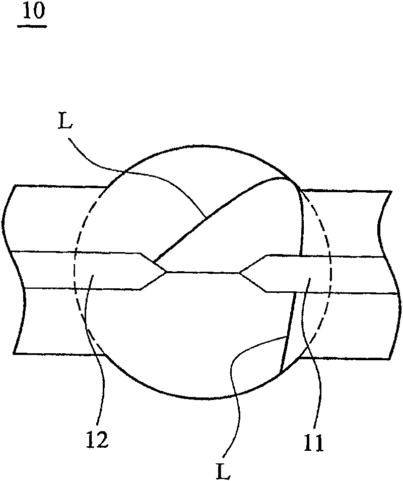
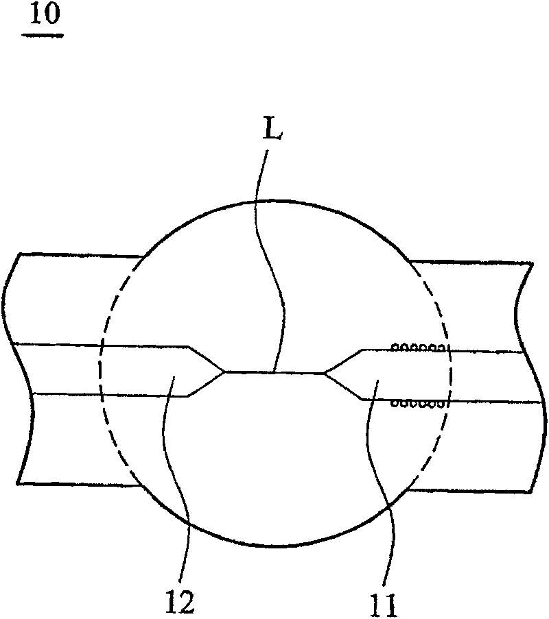
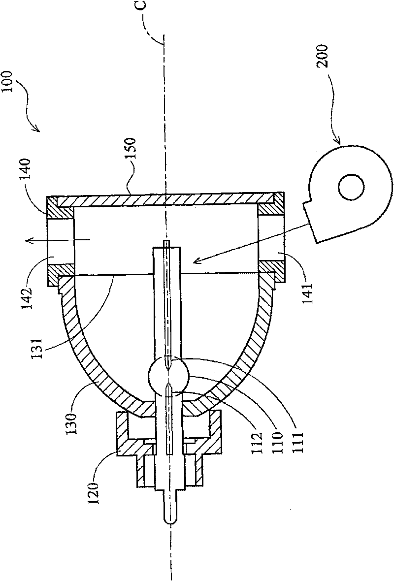
[0043] refer to Figure 2A , which shows a schematic diagram of the light source module 100 and the fan 200 inside the projector. The aforementioned light source module 100 is, for example, an ultra-high pressure mercury lamp, which mainly includes a discharge part 110, a base 120, a reflector 130, a flow guiding device 140, and a lens 150, wherein the discharge part 110 is located on the central axis C of the reflector 130 and is fixed to the base 120 , the aforementioned air guiding device 140 is connected to the reflector 130 and the lens 150 , and covers the opening 131 of the reflector 130 .

[0044] Such as Figure 2A As shown, the discharge portion 110 includes a first electrode 111 and a second electrode 112 made of metal, respectively serving as the cathode and anode of the discharge portion 110, wherein the first electrode 111 extends toward the opening 131 along the central axis C, and the second The second electrode 112 is opposite to the first electrode 111 . I...


PUM


Abstract

A method for cooling a discharging part of a light source module comprises the steps as follows: firstly, a fan at a first rotating speed cools the discharging part of the light source module to a first temperature, wherein the first temperature is approximately equal to the condensation temperature of the vapor in the discharging part; and then, when the discharging part is cooled to the first temperature, the fan at a second rotating speed cools the discharging part to a second temperature, wherein the vapor in the discharging part is coagulated at the second temperature to a special proportion, and the second rotating speed is smaller than the first rotating speed. Therefore, the invention improves the traditional cooling method to facilitate the capability of coagulation of the mercurial vapor in the discharging part (10) during the cooling process, and the mercurial vapor is coagulated in the position of the bottom part of an electrode (11) to enable an electric arc to be formed at the points (the paths with lowest impedances) of the electrode (11) and an electrode (12), so as to avoid damage to the wall of a glass tube.

Description

technical field [0001] The invention relates to a method for cooling the discharge part of a light source module, in particular to a method for cooling the discharge part of the light source module by using a fan. Background technique [0002] Ultra-high-pressure mercury lamps are often used as light sources in traditional projection devices or optical systems. Although ultra-high-pressure mercury lamps have the advantages of high brightness and high luminous efficiency, the mercury lamp will still maintain a high level within a few minutes after it is extinguished. temperature and mercury vapor pressure, so the gas discharge cannot be resumed immediately, and it must wait until the mercury vapor inside the lamp tube cools down before restarting. [0003] refer to Figure 1A , which is a schematic diagram showing the discharge unit 10 of the ultra-high pressure mercury lamp. In order to shorten the waiting time for restarting the mercury lamp, a common solution is to contin...

Claims


Application Information

Patent Timeline
Patent Type & Authority Patents(China)
IPC IPC(8): G03B21/16G03B21/00H05K7/20
Inventor 萧启宏沈俊明郑全宏
Owner QISDA CORP
Features
  • R&D
  • Intellectual Property
  • Life Sciences
  • Materials
  • Tech Scout
  • Unparalleled Data Quality
  • Higher Quality Content
  • 60% Fewer Hallucinations
Learn More