Liquefied gas reliquefier, liquefied-gas storage facility and liquefied-gas transport ship including the same, and liquefied-gas reliquefaction method

a technology of liquefied gas and liquefied gas transport, which is applied in the direction of liquefaction, container discharging methods, lighting and heating apparatus, etc., can solve the problem of requiring certain level of skill for handling, and achieve the effect of simple configuration and high redundancy

Active Publication Date: 2010-07-08
MITSUBISHI SHIPBUILDING CO LTD
View PDF13 Cites 23 Cited by
  • Summary
  • Abstract
  • Description
  • Claims
  • Application Information

AI Technical Summary

Benefits of technology

[0033]According to the present invention, because the heat exchange unit for reliquefying the BOG with the secondary refrigerant is disposed near the liquefied-gas storage tank, the liquefied gas reliquefier can be realized with a simple configuration.
[0034]I

Problems solved by technology

A conventional cooling system using a Brayton cycle, however, has a problem in that it requires a large plant to

Method used


Image

  • Liquefied gas reliquefier, liquefied-gas storage facility and liquefied-gas transport ship including the same, and liquefied-gas reliquefaction method
  • Liquefied gas reliquefier, liquefied-gas storage facility and liquefied-gas transport ship including the same, and liquefied-gas reliquefaction method
  • Liquefied gas reliquefier, liquefied-gas storage facility and liquefied-gas transport ship including the same, and liquefied-gas reliquefaction method

Examples


first embodiment

[0040]A first embodiment of the present invention will be described below using FIG. 1.

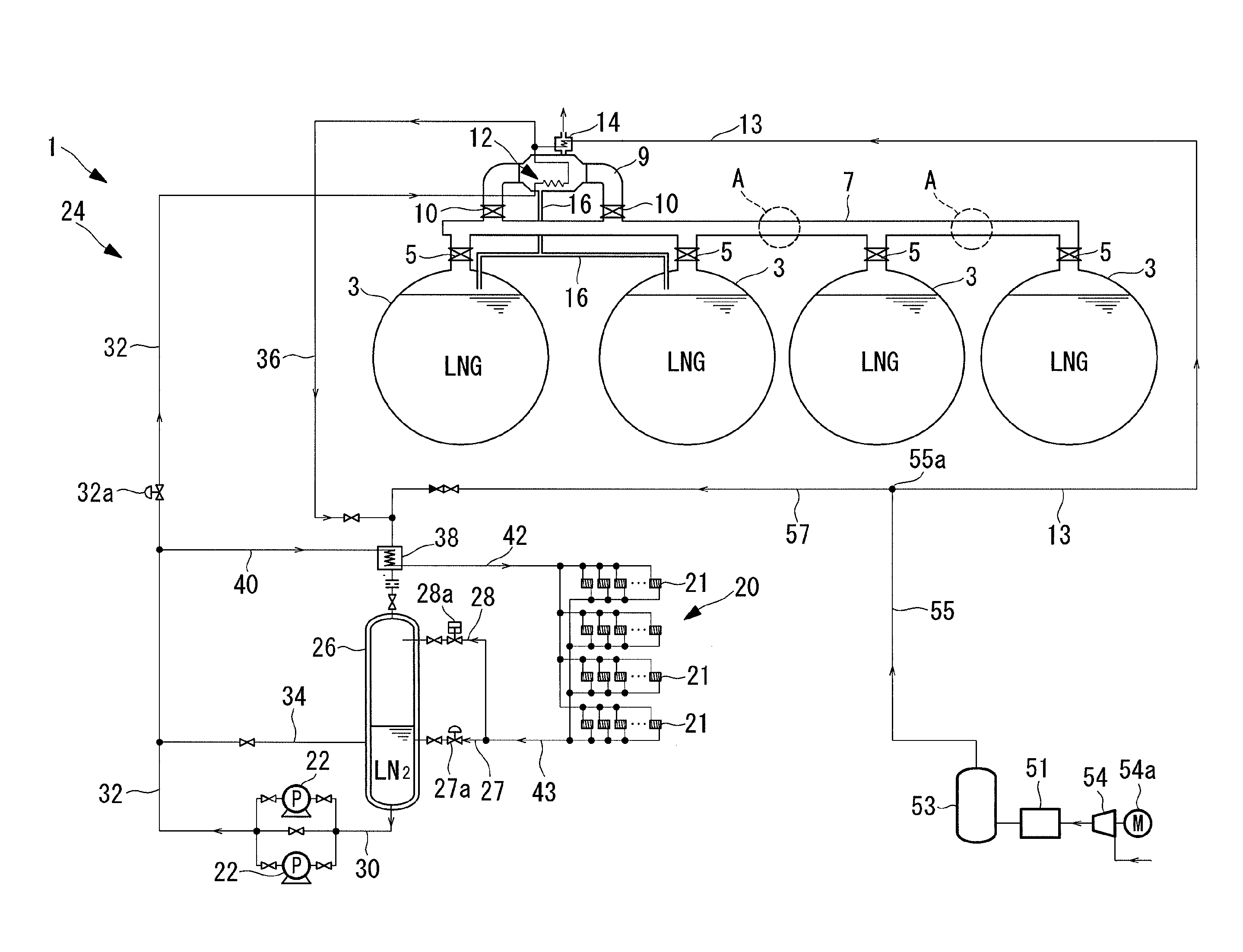
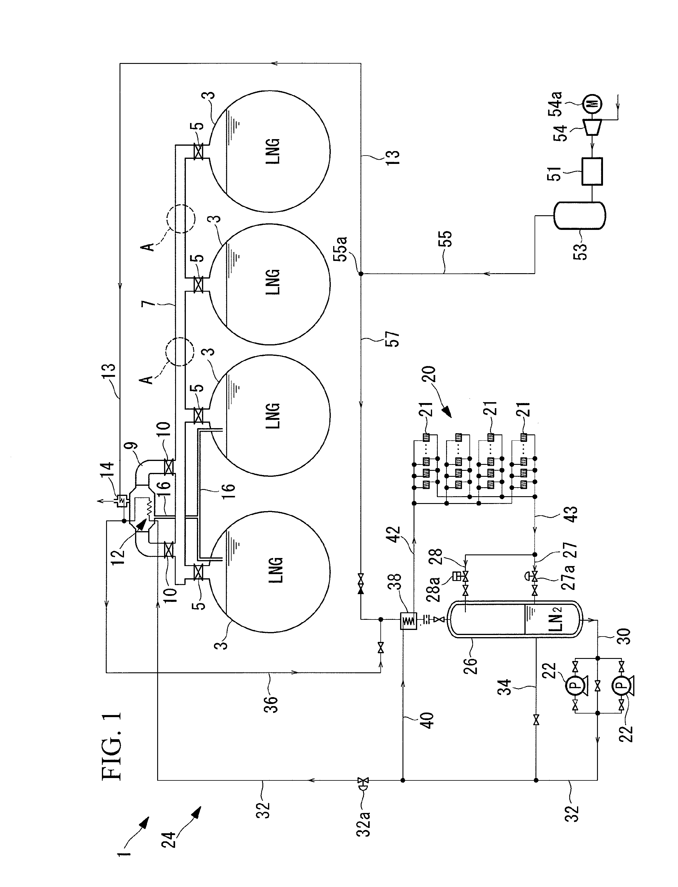
[0041]FIG. 1 shows a relevant part of an LNG ship (liquefied-gas transport ship) including a gas reliquefier 1.

[0042]The LNG ship includes a plurality of independent spherical cargo tanks (liquefied-gas storage tanks) 3, and each cargo tank 3 stores liquefied natural gas (LNG).

[0043]A vapor header line (header pipe) 7 is provided above the individual cargo tanks 3 with gate valves 5 therebetween. The vapor header line 7 is a common pipe connected to the individual cargo tanks 3 to recover BOG resulting from evaporation of the LNG in the individual cargo tanks 3 (hereinafter referred to as “BOG”). The vapor header line 7 has a bypass line (header bypass pipe) 9 extending from the vapor header line 7 in parallel therewith. Gate valves 10 are provided at both ends of the bypass line 9.

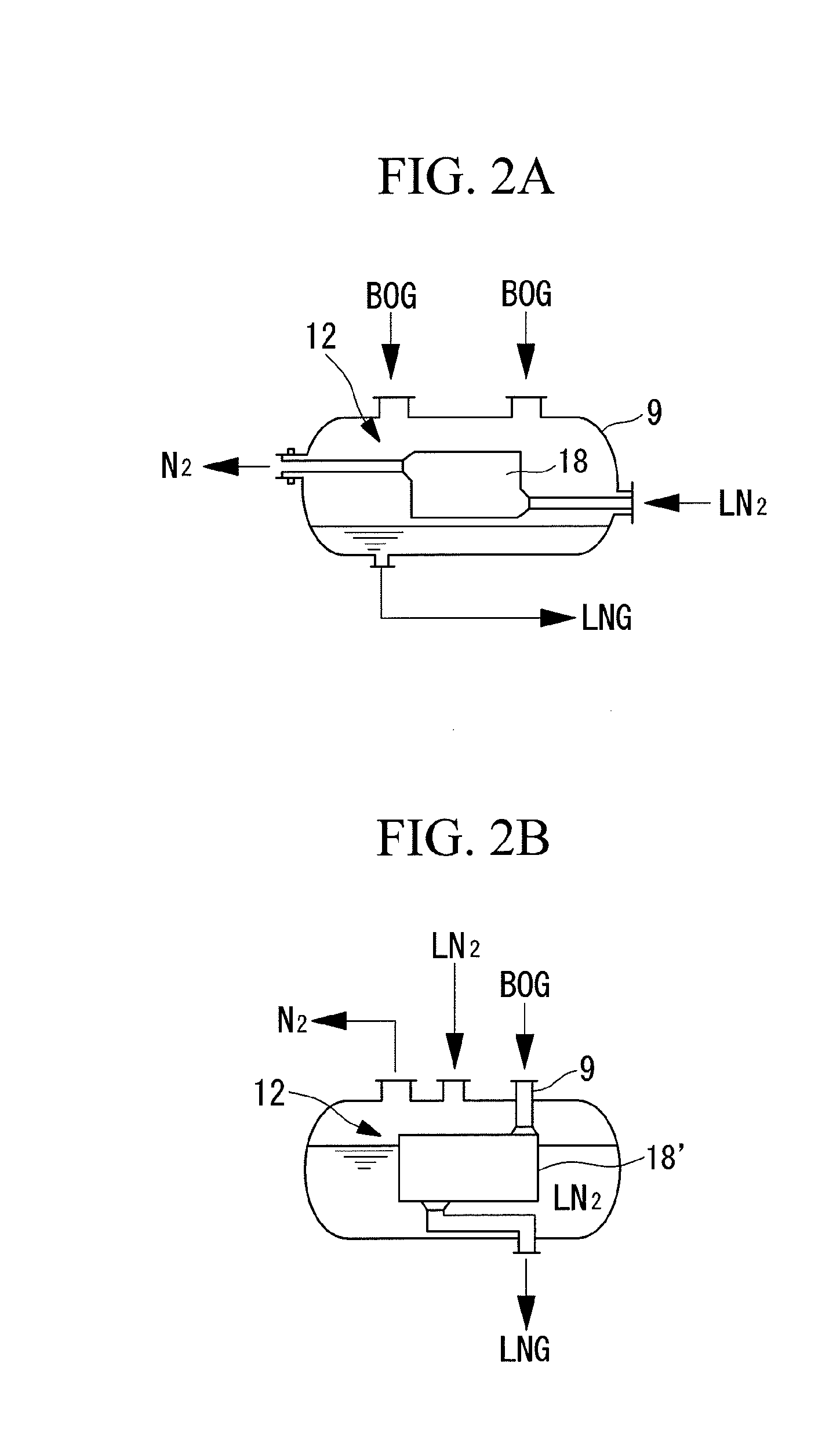
[0044]A heat exchanger 12 is accommodated in the channel of the bypass line 9, and the BOG resulting from evaporation...

second embodiment

[0083]Next, a second embodiment of the present invention will be described using FIG. 3.

[0084]This embodiment differs primarily in that it employs a natural circulation condensation system in which nitrogen gas is cooled and condensed by the refrigerator group 20, rather than a forced circulation system in which liquid nitrogen is supercooled by the refrigerator group 20, as in the first embodiment. Accordingly, the same components as in the first embodiment are indicated by the same reference signs, and a description thereof will be omitted.

[0085]In this embodiment, the nitrogen-gas return pipe 36 for returning the nitrogen gas resulting from evaporation in the heat exchanger 12 is directly connected to the vapor-liquid separation tank 26. That is, the nitrogen gas returned from the nitrogen-gas return pipe 36 is supplied into the vapor phase in the vapor-liquid separation tank 26 without passing through a heat exchanger for precooling (see reference sign 38 in FIG. 1).

[0086]The re...


PUM


Abstract

A liquefied gas reliquefier that can be configured compactly and that is easy to handle is provided. A liquefied gas reliquefier (1) reliquefies BOG resulting from evaporation of LNG in a cargo tank (3). The liquefied gas reliquefier (1) includes a refrigerator group (20) disposed in a secondary-refrigerant circulating channel (24) through which nitrogen, which has a lower condensation temperature than the BOG, circulates to liquefy the nitrogen; a feed pump (22) for feeding the liquid nitrogen cooled by the refrigerator group (20) through the secondary-refrigerant circulating channel (24); and a heat exchanger (12) disposed in the secondary-refrigerant circulating channel (24) to condense the BOG by heat exchange between the BOG and the liquid nitrogen fed by the feed pump (22). The heat exchanger (12) is disposed near the cargo tank (3).

Description

TECHNICAL FIELD[0001]The present invention relates to liquefied gas reliquefiers for reliquefying boil-off gas (hereinafter abbreviated to “BOG”) resulting from evaporation of liquefied gas such as LNG, to liquefied-gas storage facilities and liquefied-gas transport ships including such liquefied gas reliquefiers, and to liquefied-gas reliquefaction methods.BACKGROUND ART[0002]For example, LNG ships are equipped with LNG storage tanks (liquefied-gas storage tanks) storing LNG (liquefied natural gas). In the LNG storage tanks, incoming heat penetrating tank insulation evaporates the LNG to generate BOG. To keep the internal pressure of the LNG storage tanks constant while preventing a rise in the internal pressure due to the BOG, either a method of releasing the BOG to the outside air or a method of reliquefy the BOG and returning it to the LNG storage tanks is available. Typically used as the method of reliquefy the BOG and returning it to the LNG storage tanks is a method in which ...

Claims


Application Information

Patent Timeline
IPC IPC(8): F25J1/00F17C13/08
CPCB63B25/16B63B35/44F17C9/04F17C13/00F17C2265/033F25J1/0025F25J1/0052F25J1/0072F25J1/0265F25J1/0268F25J1/0271F25J1/0277F25J2235/42F25J2250/02F25J2270/908F25J2270/91F17C2201/0128F17C2201/052F17C2205/0142F17C2221/014F17C2221/033F17C2223/0161F17C2223/033F17C2265/034F17C2270/0105F25J1/0204F25J1/0262F25J1/0077
Inventor OKA, MASARUHIRAMATSU, SAIKONDO, HITOSHIOHASHI, YOSHIMASANAGAYA, SHIGEOTAMADA, TSUTOMU
Owner MITSUBISHI SHIPBUILDING CO LTD
Why Eureka
Try Eureka