
Imaging processing box

An imaging processing and box body technology, which is applied in electrography, optics, instruments, etc., can solve the problems of incomplete imaging, the protection cover cannot be opened normally, and the steps or protrusions of the protection cover are easily worn or deformed.

Inactive Publication Date: 2009-02-25
NINESTAR CORP
View PDF2 Cites 4 Cited by
  • Summary
  • Abstract
  • Description
  • Claims
  • Application Information

AI Technical Summary

Problems solved by technology

[0003] The present invention provides an imaging process box to solve the problem of paper jams and incomplete imaging due to the failure of the protective cover to be opened normally due to the steps or protrusions of the existing imaging process box being easily worn or deformed during long-term use. unusual phenomenon

Method used


Image

  • Imaging processing box
  • Imaging processing box
  • Imaging processing box

Examples


Embodiment 1

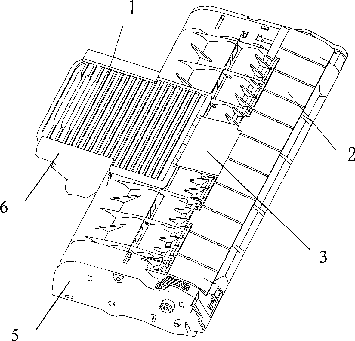
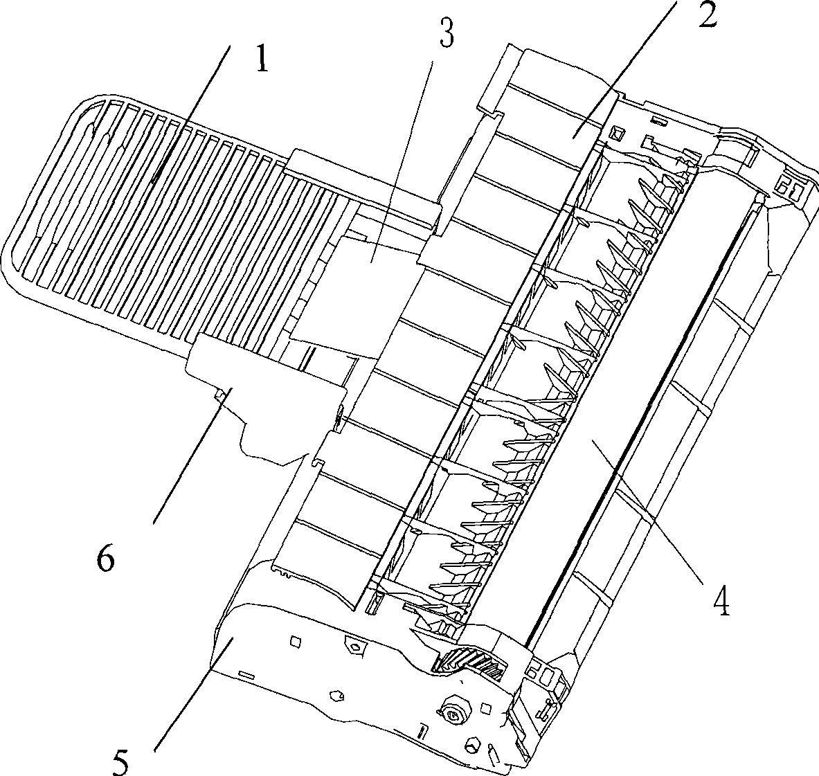
[0020] Such as figure 1 , 2 Shown, a kind of imaging processing cartridge comprises a box body 5, and protective cover 2, photosensitive drum 4, developing roller and retractable handle are installed on the box body 5, and protective cover 2 protects photosensitive drum 4 and developing roller, and photosensitive drum 4 is used to form an electrostatic latent image, and the developing roller develops the electrostatic latent image on the photosensitive drum 4. The handle includes a handle slide plate 1 and a handle support 6, and the handle support 6 is fixedly connected with the box body 5, and the two sides are respectively provided with The slideway, the handle slide 1 can slide on the slide, the protective cover 2 is erected by the box body 5 around the photosensitive drum 4, so as not to contact and wear the photosensitive drum 4, and the protective cover 2 and the handle slide 1 pass through The connecting plate 3 is hingedly connected to prevent the curved bottom of th...

Embodiment 2

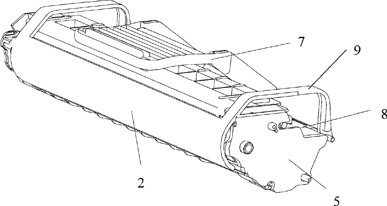
[0022] Such as image 3 , 4 Shown, a kind of imaging processing cartridge comprises a box body 5, and protective cover 2, photosensitive drum 4, developing roller and handle are installed on the box body 5, and protective cover 2 protects photosensitive drum 4 and developing roller, and photosensitive drum 4 is used for Form an electrostatic latent image, and the developing roller develops the electrostatic latent image on the photosensitive drum 4. The handle includes a handle 7, which is hingedly connected to the box body 5 through a rotating shaft 8, and the protective cover 2 is connected to the handle by the support rods 9 on both sides. 7 is connected, and the protective cover 2 is also provided with soft protective materials such as sponges for better protection of the photosensitive drum, such as image 3 The handle shown is in close contact with the box body 5, and the protective cover 2 is in a closed state; after the user unpacks the package, the user needs to hold...


PUM


Abstract

The invention relates to an imaging processing box which comprises a box body. A protective cover, a telescopic hand shank connected with the box body, a photosensitive drum and / or a developer roller are arranged on the box body; the protective cover is set up by the box body part at the periphery of the photosensitive drum, so as to protect the photosensitive drum and / or the developer roller; the photosensitive drum is used for forming an electrostatic latent image, and the developer roller is used for developing the electrostatic latent image on the photosensitive drum; and the protective cover is connected with the hand shank and in movable linkage with the hand shank. After unpacking, users need to put the imaging processing box in an electronic imaging device by holding the hand shank by hands for use; meanwhile, the hand shank is moveably opened under the self-gravity action of the imaging processing box, and the protective cover is opened under the linkage action of the hand shank. Therefore, the abnormal phenomena that the prior imaging processing box is easily worn or deformed due to the opening of a step or a protrusion of the protective cover in the long-term use process, so that the protective cover cannot be opened normally, and paper jam and incomplete imaging appear.

Description

technical field [0001] The present invention relates to an image forming process cartridge. Background technique [0002] In the prior art, the process cartridge of a common electronic imaging device includes a box body on which a protective cover, a photosensitive drum and a developing roller are installed, and the protective cover is partially erected by the box body around the photosensitive drum to protect the photosensitive drum and the developing roller. The photosensitive drum is used to form an electrostatic latent image, and the developing roller develops the electrostatic latent image on the photosensitive drum. In order to avoid the photosensitive drum in the imaging process box from being polluted or exposed during transportation, as US Patent No. 4,462,677 and US 4,470,689 disclose a movable protective cover to protect the photosensitive drum; When it is in the middle, the protective cover is opened by the steps or protrusions in the electronic imaging device, ...

Claims


Application Information

Patent Timeline
Patent Type & Authority Applications(China)
IPC IPC(8): G03G21/18
Inventor 彭庆菲刘金莲
Owner NINESTAR CORP
Learn More