
Directly-drive ball top type loudspeaker

A loudspeaker, direct technology, applied in the field of structural improvement of dome loudspeakers, can solve the problems of difficult sound film processing, deterioration of high-frequency response, decreased sensitivity, etc., to improve high-frequency response characteristics, reduce vibration quality, and eliminate weight Effect

Inactive Publication Date: 2012-09-26
张百良
View PDF1 Cites 0 Cited by
  • Summary
  • Abstract
  • Description
  • Claims
  • Application Information

AI Technical Summary

Problems solved by technology

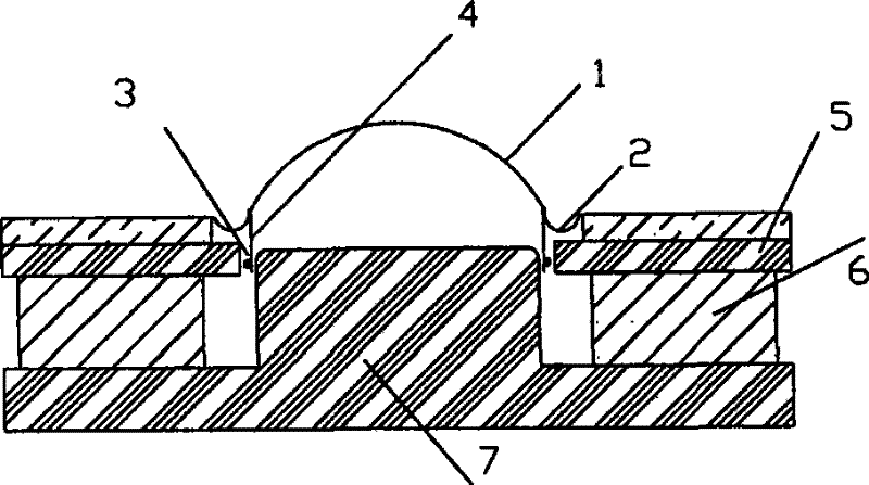
[0005] One is that the processing of the sound film is more difficult, because the heat setting of this narrow deep groove is more complicated, and it is necessary to ensure the accuracy of the inner and outer diameters and depths. For many materials such as fabrics or metal films, it may be difficult to achieve. Generally, only The technology can be implemented using a polymer resin film for heat setting, which places a limit on the performance of the loudspeaker
[0006] The second is that the voice coil is wrapped in the middle by glue and the annular voice coil frame, which is not conducive to the heat dissipation of the voice coil
Therefore, the risk of burning the voice coil due to high temperature is greatly increased when using high power
For general loudspeakers, the power of 10-20W is often required, and the temperature at the voice coil often reaches 200°C or higher. For this structure that is not conducive to heat dissipation, the temperature of the voice coil will be even higher. The sound film material of the polymer resin film is generally used at a temperature of only about 100°C, which limits this structure to only be suitable for some low-power applications, such as the receiver of the portable phone described in CN1222049A. Occasions with low requirements and compact structure
[0007] The third is the restriction on the shape of the folding ring
Since there is a magnetic pole plate under the ring, in order to ensure that the speaker has sufficient amplitude, it can only adopt the shape of a convex ring. To fill a lot of glue, the increase in mass will bring unacceptable sensitivity drop and high frequency response degradation

Method used


Image

  • Directly-drive ball top type loudspeaker
  • Directly-drive ball top type loudspeaker
  • Directly-drive ball top type loudspeaker

Examples


Embodiment 1

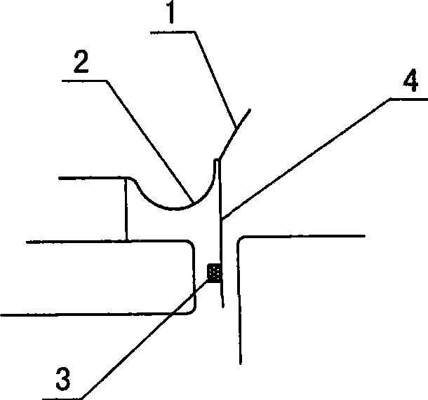
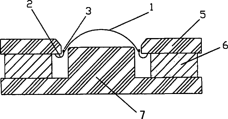
[0031] The structure of this direct drive dome loudspeaker embodiment is as follows image 3 As shown, it includes the magnetic circuit structure of the loudspeaker composed of T-shaped iron parts 7, annular permanent magnet steel 6, and annular magnetic conductive sheet 5. It has a convex dome-shaped sound membrane 1 and its connected concave fold ring 2. A wire-wound voice coil 3 is directly formed on the sound membrane surface at the junction of the top sound membrane 1 and the concave fold ring 2 (such as Figure 4 As shown), the convex dome sound membrane 1 is to use the same 28-core silk (or fabric) dome sound membrane of the traditional dome speaker, in which a convex dome is in the middle, and the outside is anti-concave The semicircular ring 2 is made of cloth and heat-pressed after resin treatment. The diameter of the connection between the convex ball top sound film 1 and the concave fold ring 2 is about 28mm, and there is a corner at this place, where a 0.06mm dia...

Embodiment 2

[0033] The magnetic circuit structure of the embodiment of the direct drive dome speaker is basically the same as that of Embodiment 1, and has the substantially same convex dome-shaped sound membrane 1 and its connected concave folding ring 2, where the convex dome sound membrane 1 and the A wire-wound voice coil 3 is directly formed on the surface of the sound membrane at the junction of the concave fold ring 2, and the wire-wound voice coil 3 is braided into five enameled wires with a diameter of 0.06 mm on the fabric dome sound membrane 1 to form a braided Wirewound voice coils (such as Figure 7 shown).

Embodiment 3

[0035] The structure of this direct drive dome loudspeaker embodiment is as follows Figure 8 As shown, it includes a magnetic circuit structure composed of a magnetic pole plate 9 and two magnetic steels (upper magnetic steel 8 and lower magnetic steel 10). Combined, a magnetic circuit for the loudspeaker is formed with radial magnetic fields converging near the sides of the pole plates. An iron flat plate 11 is arranged below the lower magnetic steel to strengthen the magnetic field and reduce magnetic leakage. It also has a convex dome-shaped sound film 1 and its connected concave fold ring 2. The sound film surface at the junction of the convex dome sound film 1 and the concave fold ring 2 is fixed with a wire-wound voice coil 3. The wire-wound voice coil 3. Use the pre-wound coil to directly fix it at this place. The convex dome sound film 1 uses the same 28-core silk (or fabric) dome sound film as the traditional dome speaker, and the middle is A convex dome, the outsi...


PUM


Abstract

The invention provides a direct drive global roof type loudspeaker, which includes a loudspeaker magnetic circuit structure which could generate a circle belt shaped radial permanent magnetic field, and a convex global roof shaped sound film and a corrugated rim connected therewith. The invention is characterized in that a wire-wound speech coil is directly formed on the sound film surface which is on the connection of the sound film global roof and the corrugated rim. Technically the speech coil is a lead for coating the insulating layer, and the speech coil can be directly coiled on the connection, or a pre-coiled coil which is directly fixed on the connection. Particularly, when the chose sound film is a textile sound film, the coil could be a lead for coating the insulating layer, which is weaved on the connection in the mode similar to sewing, thereby strengthening the integration of the sound film and the speech coil. The loudspeaker has the advantages of flat membrane type direct drive wide frequency response, free material-choosing of the global roof type sound film, graceful timbre, and wire-wound speech coil with small volume, high efficiency and uniform magnetic field or the like.

Description

technical field [0001] The invention relates to a structural improvement of a dome speaker. Background technique [0002] The existing dome loudspeaker has a structure such as figure 1 As shown, it includes the magnetic circuit structure of the loudspeaker composed of T-shaped iron parts (7), ring-shaped permanent magnet steel (6), and ring-shaped magnet-conducting sheet (5), a dome-shaped sound membrane (1), and a ring (2). , bobbin (4) and voice coil (3). The dome-shaped sound film can be concave or convex, and it is assembled in the center of the speaker. , diamond, ceramics and other hard shell materials, and are called soft dome speakers and hard dome speakers respectively. The outer edge of the sound film is a ring, which is generally semicircular, with both convex upward and concave downward. The ring provides the compliance and amplitude of vertical vibration, and also provides horizontal "centering" to prevent vibration. The sound film and the voice coil have la...

Claims


Application Information

Patent Timeline
Patent Type & Authority Patents(China)
IPC IPC(8): H04R9/02H04R9/06
Inventor 张百良
Owner 张百良
Learn More