
Micromechanical detection structure and MEMS inertial measurement device

A detection structure, micro-mechanical technology, applied in the field of MEMS devices, to achieve the effects of reducing stress mismatch, improving thermal drift, and reducing the radius of rotation

Active Publication Date: 2021-05-25
THE 13TH RES INST OF CHINA ELECTRONICS TECH GRP CORP
View PDF12 Cites 0 Cited by
  • Summary
  • Abstract
  • Description
  • Claims
  • Application Information

AI Technical Summary

Problems solved by technology

[0004] The purpose of the present invention is to provide a micro-mechanical detection structure and MEMS inertial measurement device, which aims to greatly improve and reduce the technical problem of cross acceleration error existing in the existing single-axis MEMS inertial measurement device

Method used


Image

  • Micromechanical detection structure and MEMS inertial measurement device
  • Micromechanical detection structure and MEMS inertial measurement device
  • Micromechanical detection structure and MEMS inertial measurement device

Examples


Embodiment Construction

[0029] In order to make the technical problems, technical solutions and beneficial effects to be solved by the present invention clearer, the present invention will be further described in detail below in conjunction with the accompanying drawings and embodiments. It should be understood that the specific embodiments described here are only used to explain the present invention, not to limit the present invention.

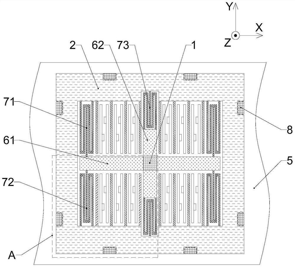
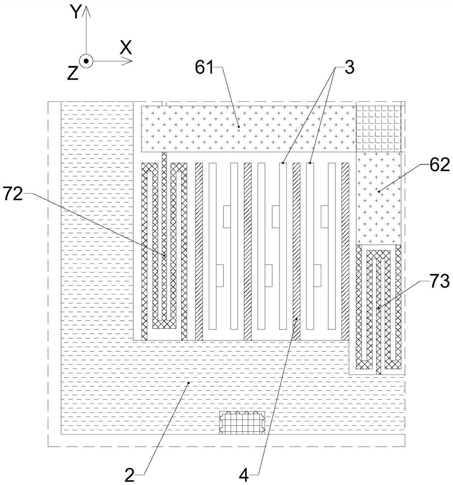
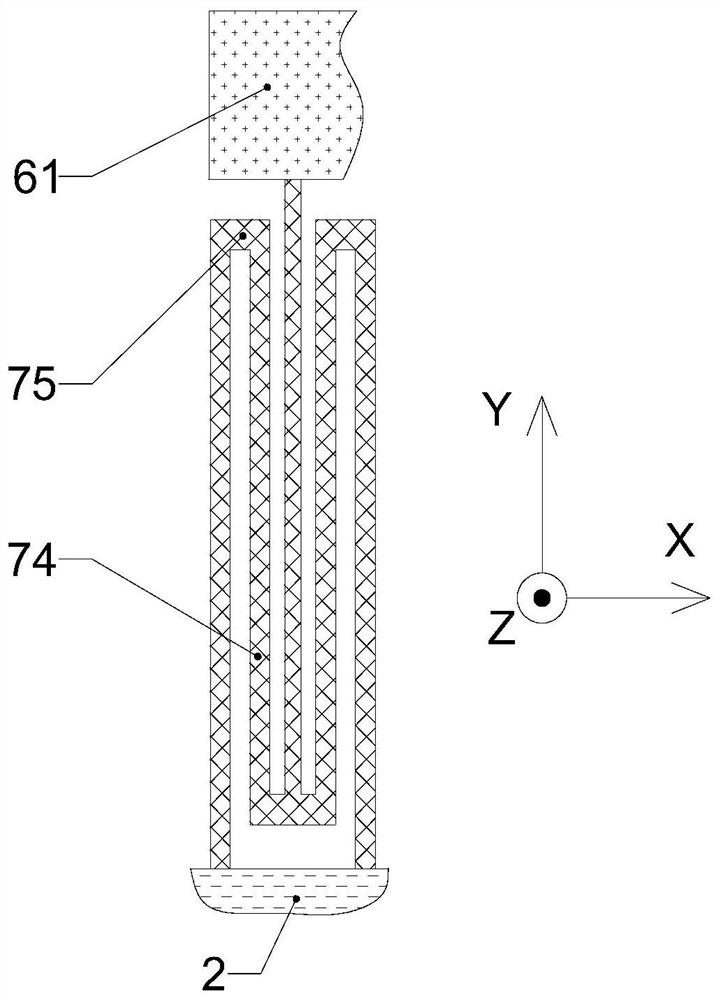
[0030] Please also refer to figure 1 and figure 2 , the micromechanical detection structure provided by the present invention will now be described. The micromechanical detection structure includes a central anchor point 1, a connecting beam, a vibration mass 2, a fixed electrode 3 and a movable electrode 4. The central anchor point 1 is used to be fixed on the substrate 5, and one end of the connecting beam is fixedly connected to the central anchor point 1. The other end protrudes to the outside of the central anchor point 1; the vibrating mass 2 has a frame-s...


PUM


Abstract

The invention provides a micromechanical detection structure and an MEMS inertial measurement device, and belongs to the technical field of MEMS devices. The micromechanical detection structure comprises a central anchor point, a connecting beam, a vibration mass, a fixed electrode and a movable electrode, wherein the central anchor point is fixedly arranged on a substrate, one end of the connecting beam is fixedly connected with the central anchor point, and the other end of the connecting beam extends out of the outer side of the central anchor point; the vibration mass is of a frame-shaped structure and is located on the periphery of the central anchor point, the vibration mass is connected with the extending end of the connecting beam through an elastic element, the expected deformation direction of the elastic element is parallel to the sensitive shaft, the fixed electrode is fixedly arranged on the substrate, and the movable electrode is fixedly connected to the vibration mass. The movable electrode is adjacent to the fixed electrode and forms a capacitor unit with the fixed electrode, and the movable electrode moves along with the vibration mass, so that the distance between the movable electrode and the fixed electrode is changed. According to the micro-mechanical detection structure and the MEMS inertial measurement device provided by the invention, the technical problem of cross acceleration error of the existing single-axis MEMS inertial measurement device can be greatly improved and reduced.

Description

technical field [0001] The invention belongs to the technical field of MEMS devices, and more specifically relates to a micromechanical detection structure and a MEMS inertial measurement device. Background technique [0002] MEMS stands for Micro-Electro-Mechanical System, which is a science based on microelectronics, micromechanics and material science to research, design and manufacture micro-devices with specific functions. MEMS devices have a series of advantages such as small size, light weight, and high reliability, and because their processing technology is compatible with traditional integrated circuit technology to a certain extent, it is easy to achieve mass production, so it can be widely produced and applied. [0003] MEMS capacitive acceleration sensors include micro-mechanical detection structures and signal conditioning circuits. The micromechanical detection structure includes vibration mass and detection electrodes. When acceleration is input, the vibratio...

Claims


Application Information

Patent Timeline
Patent Type & Authority Applications(China)
IPC IPC(8): G01P15/125B81B7/02
CPCG01P15/125B81B7/02B81B2201/0235
Inventor 张志勇杨拥军罗蓉
Owner THE 13TH RES INST OF CHINA ELECTRONICS TECH GRP CORP
Learn More