
Desulfurized dust collector with multiple water films

A technology of water film desulfurization and dust removal, desulfurization and dust removal, which is applied in the direction of combined devices, dispersion particle separation, chemical instruments and methods, etc., can solve the problems of failing to meet environmental protection requirements, unable to eliminate harmful gases, single function of dust removal equipment, etc., and achieve saving Cleaning liquid, low cost, reasonable structure effect

Inactive Publication Date: 2009-03-04
NORTHEAST DIANLI UNIVERSITY
View PDF0 Cites 8 Cited by
  • Summary
  • Abstract
  • Description
  • Claims
  • Application Information

AI Technical Summary

Problems solved by technology

The bag-type, cyclone-type and electrostatic dust-removal devices only have dust-removal functions and cannot eliminate harmful gases in the flue gas; water-film-type, spray-type and water-bath types are wet-type dust-removal devices, which have dual functions of dust removal and filtering harmful gases. However, the existing water membrane devices suitable for flue gas desulfurization and dust removal can only be used in new large-scale power plants due to their complex structure and high cost.
Although small and medium-sized industrial coal-fired boilers cause dust and SO 2 One of the important sources of pollution, and the existing dust removal equipment for small and medium-sized industrial coal-fired boilers has a single function, the dust removal efficiency is generally low, and it is not suitable for desulfurization, which cannot meet the increasing environmental protection requirements

Method used


Image

  • Desulfurized dust collector with multiple water films
  • Desulfurized dust collector with multiple water films
  • Desulfurized dust collector with multiple water films

Examples


Embodiment Construction

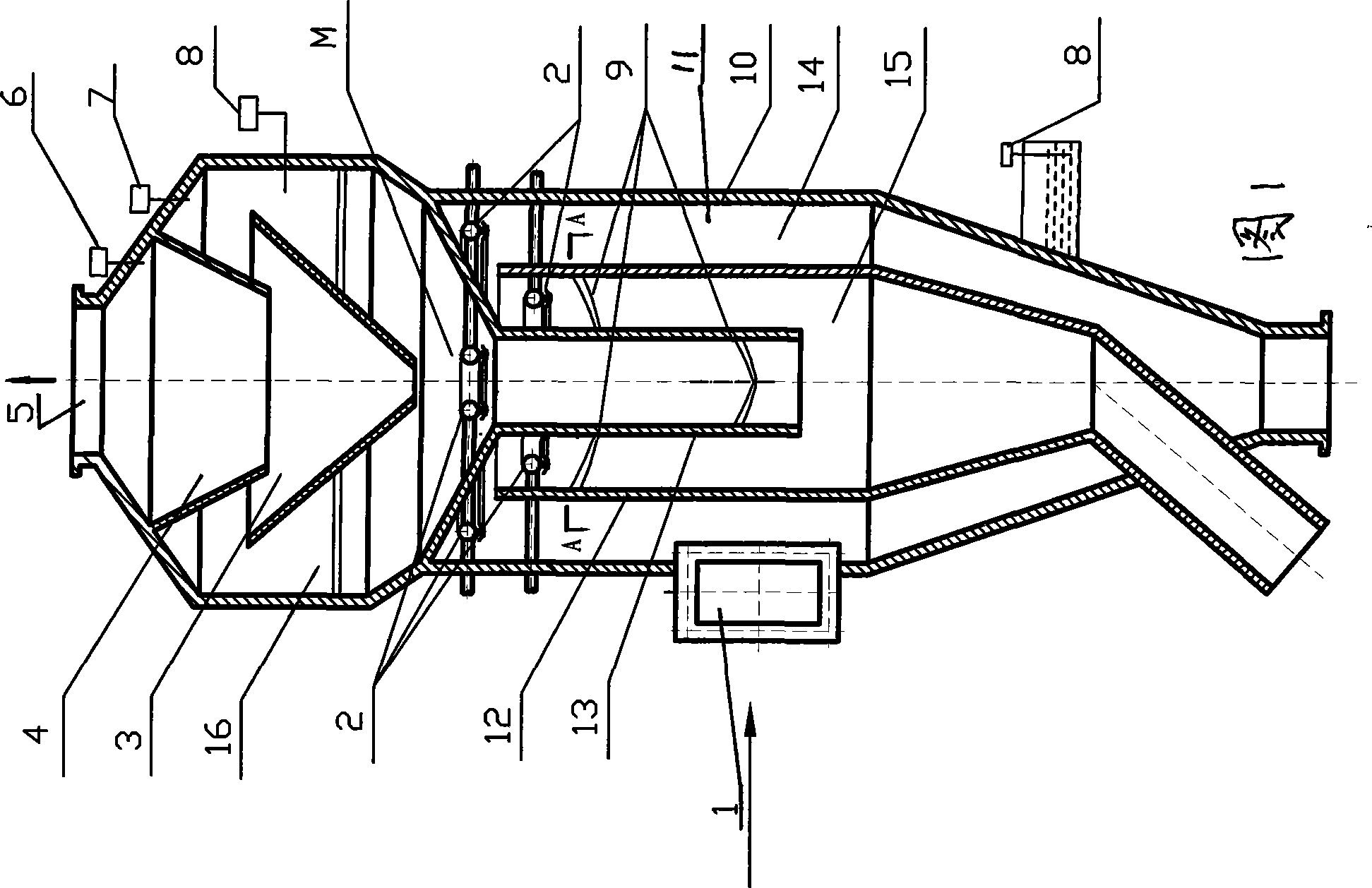
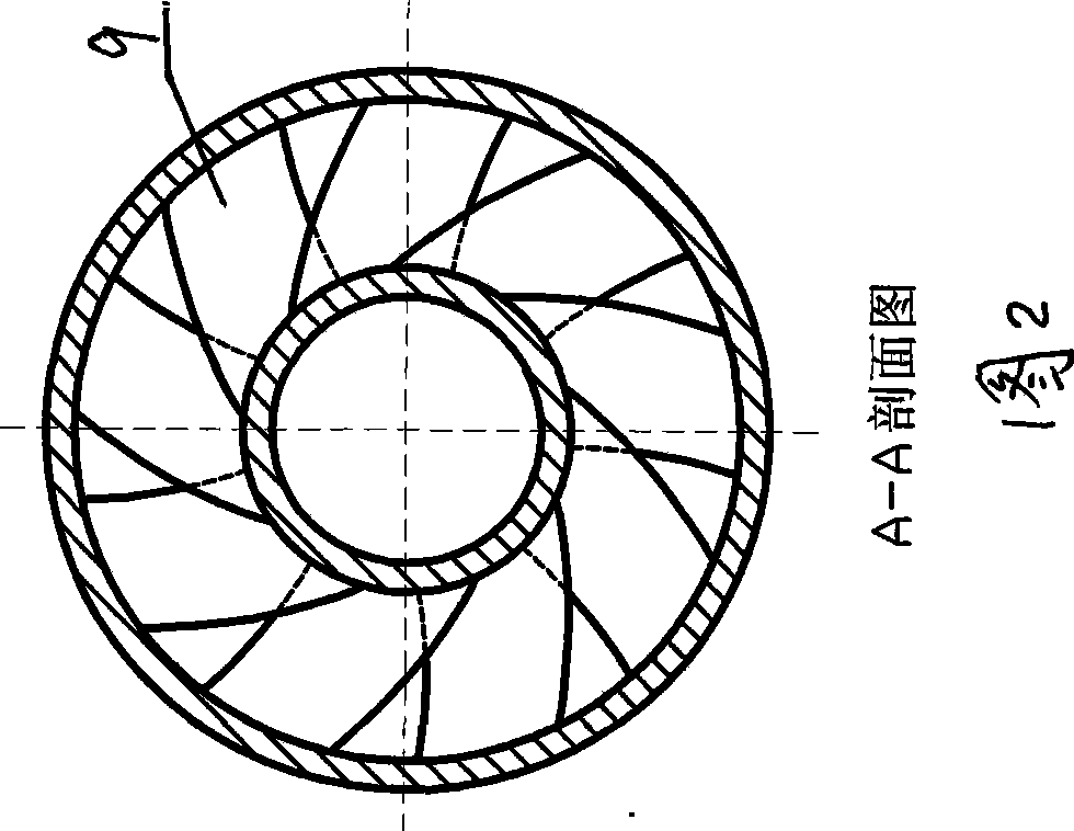
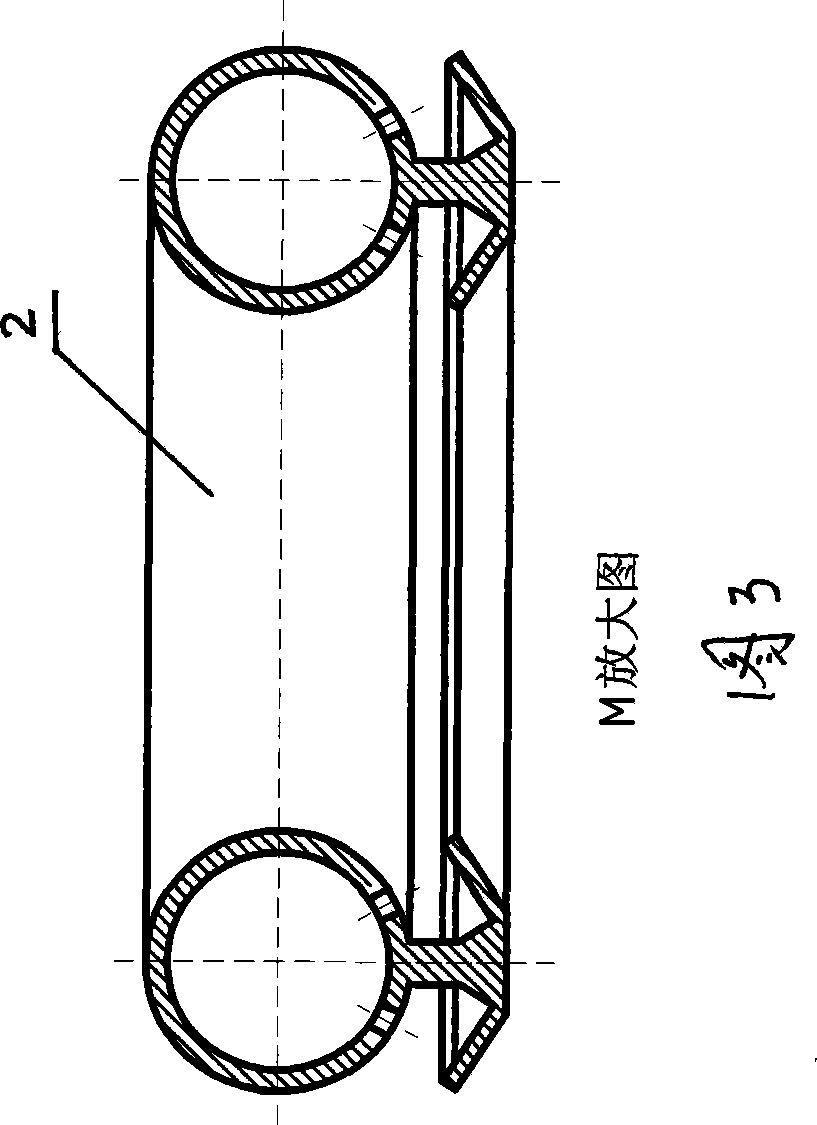
[0018] Referring to Figures 1 to 3, the multi-water film desulfurization and dust removal device has a body 10, a flue gas inlet 1 is arranged tangentially on the side wall of the body 10, a purified flue gas outlet 5 is arranged on the top of the body 10, and a water film desulfurization device is arranged in the body 10. Dust collector 11, the structure of the water film desulfurization dust collector 11 is the outer interlayer 14 formed between the body 10 and the built-in compartment 12 of the body 10, and the middle interlayer formed by the compartment 12 and the central tube 13 built in the compartment 12 15 and the central pipe 13, the outer interlayer 14, the intermediate interlayer 15 and the central pipe 13 are connected, and the annular water film generator 2 is arranged above the outer interlayer 14, the intermediate interlayer 15 and the central pipe 13, and the top in the body 10 is provided with The demisting dehumidifier 16 communicated with the central pipe 13 ...


PUM


Abstract

The invention relates to a multiple water film desulfurating and dust-removing device, which comprises a main body, with a fume gas inlet tangentially arranged on the side wall of the main body and a fume gas outlet arranged at the top of the main body. A water film desulfurating and dust-removing device is arranged in the body. The water film desulfurating and dust-removing device comprises the following structure: an outer interlayer is formed between the main body and a separating cylinder which is arranged in the main body; a middle layer is formed between the separating cylinder and a central tube which is arranged in the separating cylinder; the middle interlayer is connected with the central tube and the outer layer; an orbicular water film generator is arranged above the outer interlayer, the middle interlayer and the central tube; a demisting dehumidifier arranged at the upper part in the main body is connected with the central tube of the water film desulfurating and dust-removing device; the demisting dehumidifier comprises at least one layer of cone arranged at the upper part in the main body; the demisting dehumidifier is connected with the fume gas outlet; and gapped swirl guiding plates are arranged on laminations in the middle interlayer and the central tube. The desulfurating and dust-removing device has the advantages of reasonable structure, high desulfurating and dust-removing rate, good effect, environmental friendliness, etc.

Description

technical field [0001] The invention relates to the technical field of combustion product treatment, more specifically, a multi-water film desulfurization and dust removal device. Background technique [0002] Existing flue gas desulfurization (FGD) is to control SO 2 The main technical means of pollution is to use various alkaline absorbents or adsorbents to capture SO in the flue gas 2 , There are three main flue gas desulfurization methods: (1) dry method, using powdered or granular absorbents, adsorbents or catalysts to remove SO 2 ; (2) Wet method, which uses liquid absorbent to wash to remove SO 2 ; (3) semi-dry method, absorbent desulfurization and treatment of desulfurization products are carried out in wet state and dry state respectively. Among them, the wet washing method is dominant, accounting for about 85%. [0003] Existing flue gas dedusting mainly adopts bag type dedusting, mechanical dedusting, electric dedusting and wet dedusting; currently domestic du...

Claims


Application Information

Patent Timeline
Patent Type & Authority Applications(China)
IPC IPC(8): B01D53/78B01D53/50B01D50/00
Inventor 吕太王磊卢洪波吕勇兴
Owner NORTHEAST DIANLI UNIVERSITY
Learn More