

Fan impeller
A fan wheel and hub technology, which is applied to the components of pumping devices for elastic fluids, non-variable displacement pumps, machines/engines, etc. Increase the difficulty of manufacturing and other issues to avoid uneven weight, improve balance accuracy, and save materials
- Summary
- Abstract
- Description
- Claims
- Application Information
AI Technical Summary
Problems solved by technology
Method used
Image

Examples
Embodiment Construction
[0016] In order to make the above-mentioned and other objects, features and advantages of the present invention more comprehensible, the preferred embodiments of the present invention will be specifically cited below, together with the accompanying drawings, as follows:
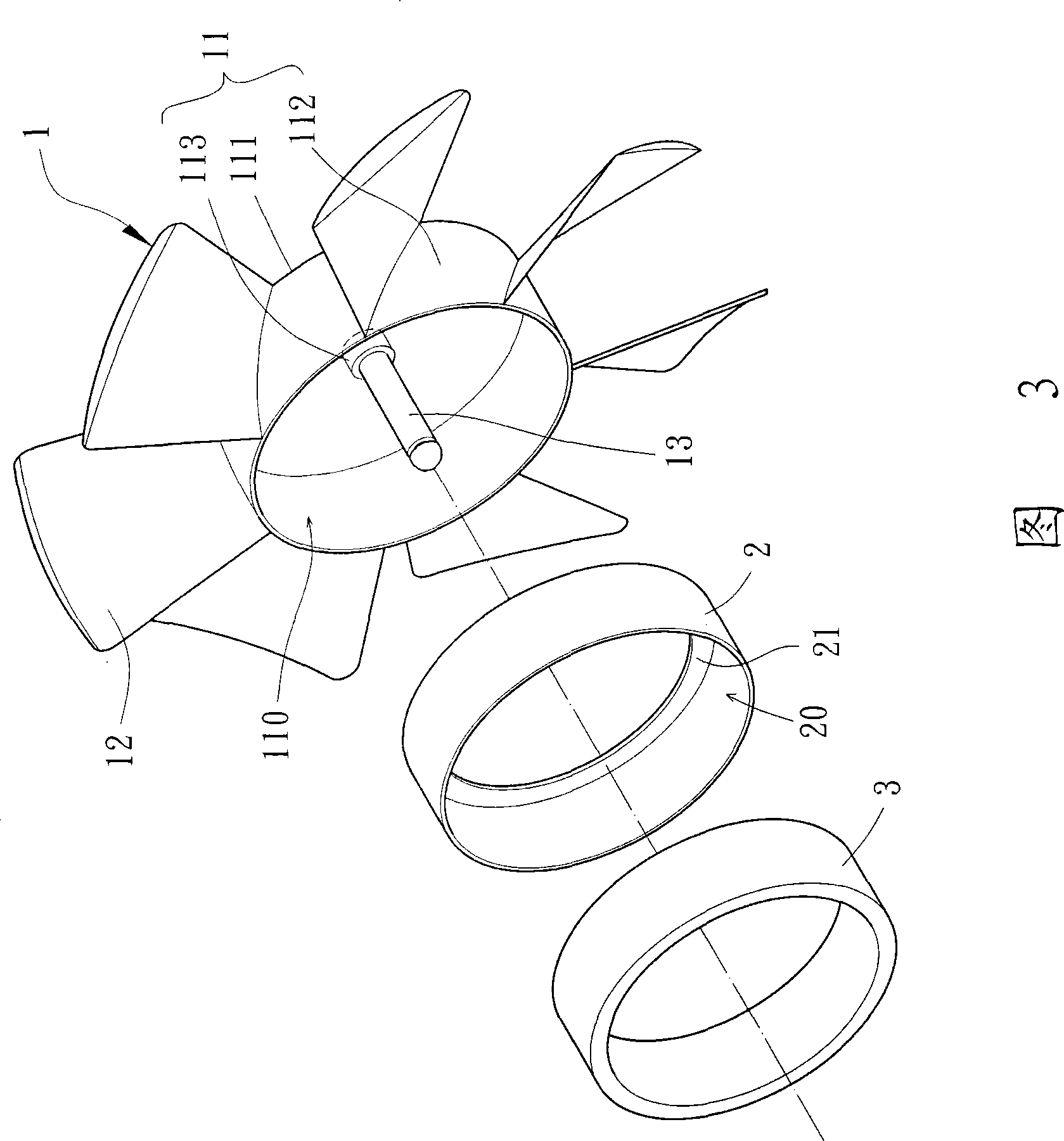
[0017] Please refer to FIG. 3, the first embodiment of the present invention: the fan wheel 1 is made of a plastic material (such as polyphenylene sulfide, polypropylene, resin, polyetheretherketone, etc.) by injection molding, and It can be selected as an axial-flow fan wheel or a blower-type fan wheel. The fan wheel 1 of this embodiment is an axial-flow fan wheel as an example of implementation. The fan wheel 1 has a hub 11, several fan blades 12 and a shaft 13, the hub 11 is in the shape of a hollow cylinder; the fan blades 12 are connected to the outer peripheral surface of the hub 11 in an equidistant arrangement; The shaft 13 is coupled to the center of the hub 11 .
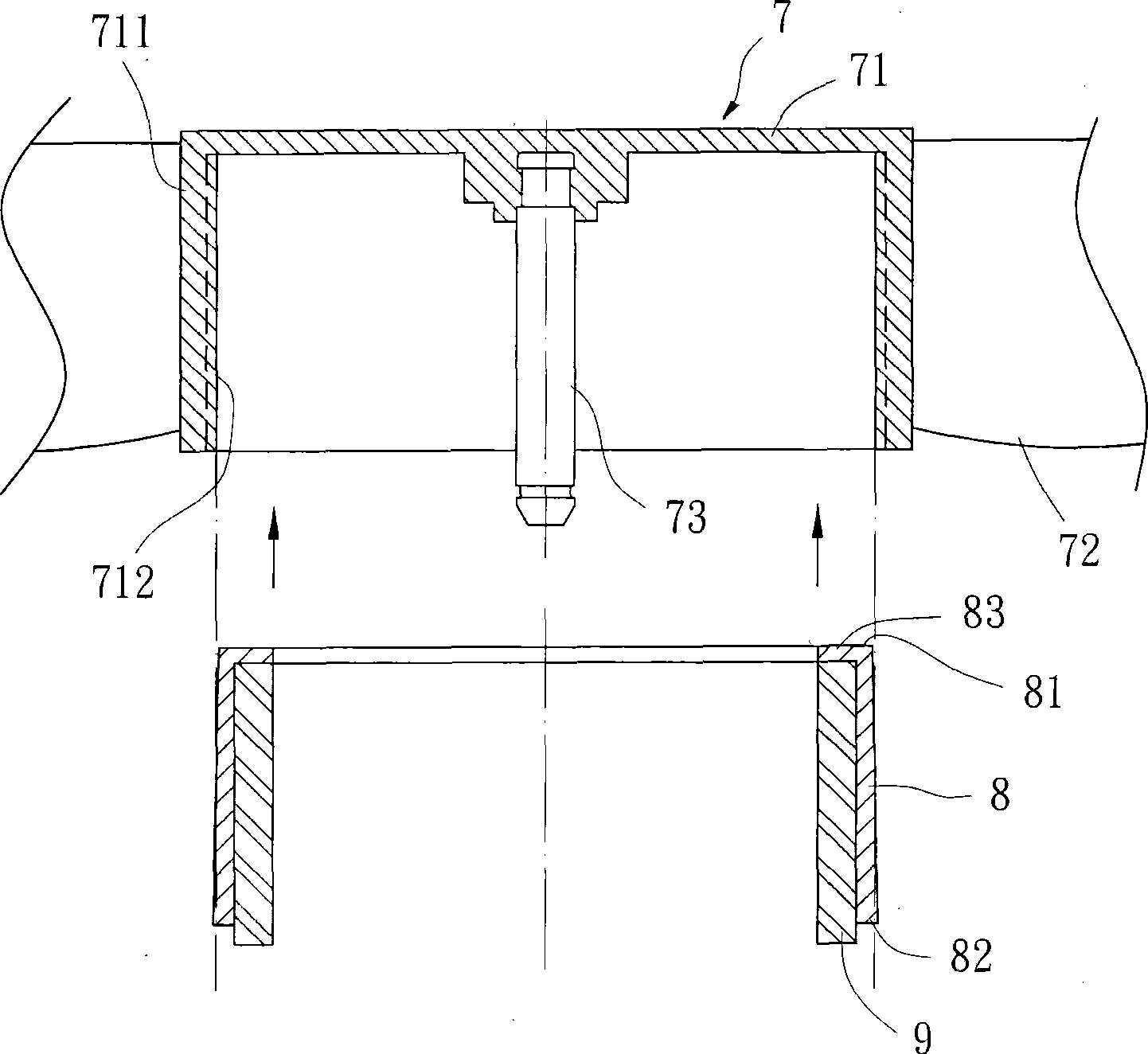
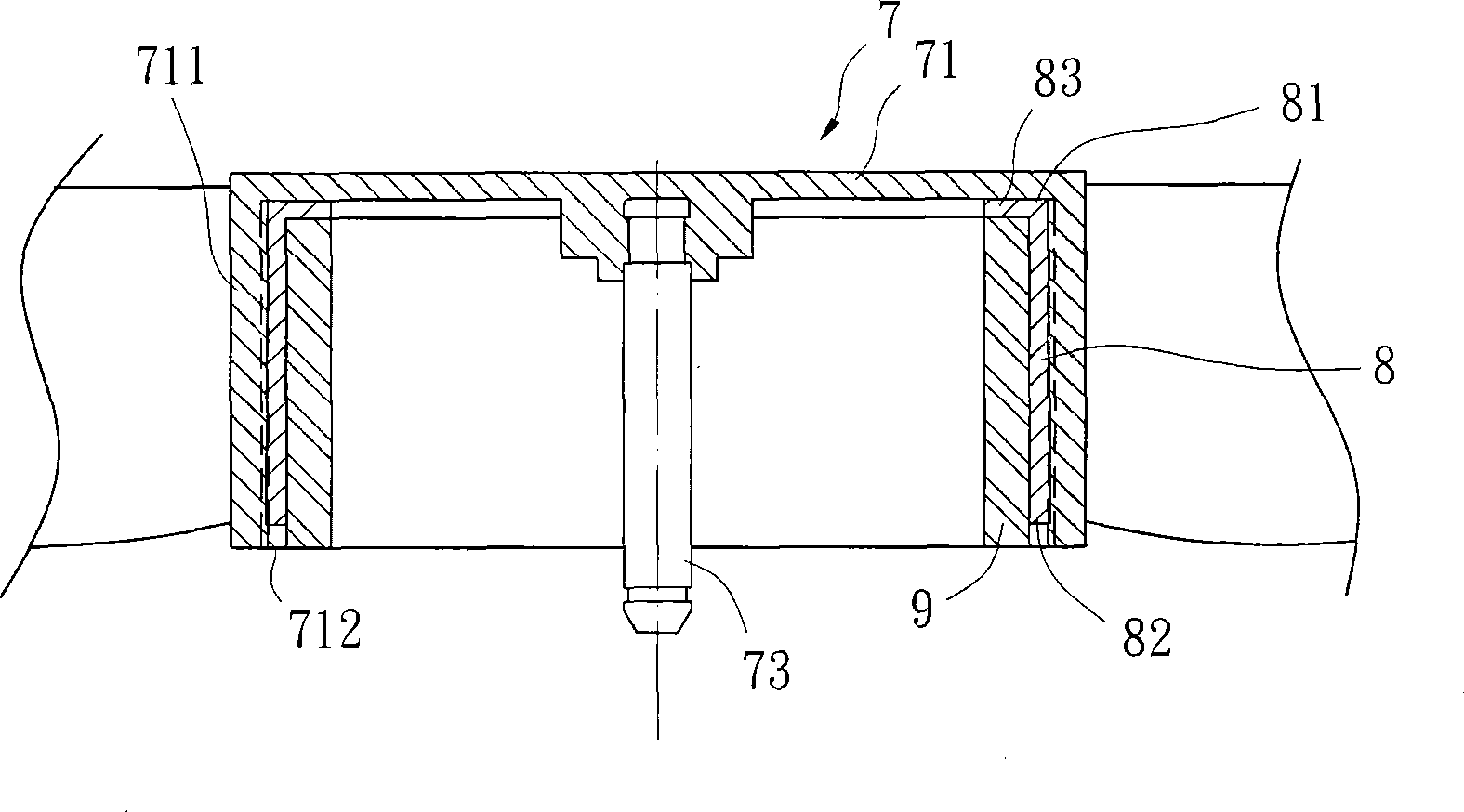
[0018] 3 and 4, the hub 11 of the ...
PUM
 Abstract
Description
Claims
Application Information