Drive circuit for high speed switch tube floating grid

A floating gate, driving circuit technology, applied in circuits, electronic switches, transistors, etc., can solve the problems of difficult application of circuits, narrow working linear region, gate drive operating frequency, voltage amplitude and duty cycle limitations, etc. Achieving the effect of convenient wide application, low circuit cost, and increased flexibility

Inactive Publication Date: 2009-03-04
深圳市圣美歌科技有限公司
View PDF0 Cites 21 Cited by
  • Summary
  • Abstract
  • Description
  • Claims
  • Application Information

AI Technical Summary

Problems solved by technology

The requirements of high withstand voltage and high speed pose a great challenge to the existing semiconductor technology, so this kind of circuit is difficult to apply in the occasion where the operating voltage difference between the driving circuit and the MOSFET exceeds 1000V
[0011] (4). figure 1 The solutions shown are usually implemented by ASICs (mainly the IR21xx series of IR Company), which makes it difficult for engineers to make targeted adjustments to the circuits according to actual application conditions.
[0014] Since this drive circuit uses tra

Method used


Image

  • Drive circuit for high speed switch tube floating grid
  • Drive circuit for high speed switch tube floating grid
  • Drive circuit for high speed switch tube floating grid

Examples


Embodiment Construction

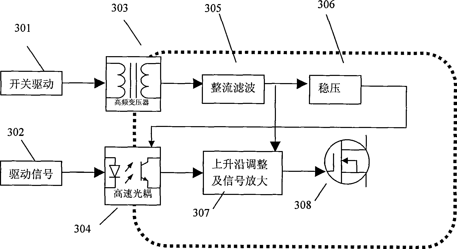
[0032] In the following description, MOSFET is still taken as an example for illustration. The principle block diagram of the present invention is as image 3 shown. The basic principle of its work is to use the source (S) of the MOSFET as a floating ground, and process the driving signal 302 through a high-speed optocoupler into a driving signal based on the floating ground; the high-frequency transformer 303 driven by the switching signal 301 provides a floating ground. The reference ground of the power supply is also the floating ground; after the rectification and filtering 305, the floating power supplies power to the rising edge adjustment and signal amplification circuit 307, and at the same time supplies power to the optocoupler 304 through the voltage stabilizing circuit 306. The rising edge adjustment and signal amplifying circuit 307 can output a floating driving signal based on the floating ground and whose rising edge speed can be adjusted. image 3 Each circuit...


PUM


Abstract

The invention relates to a high speed switching tube floating grid driving circuit, aiming at solving the technological problem of the existing switching tube floating grid driving circuit that duty ratio is limited, and the like. In the invention, the source electrode of MOSFET or the emitter of IGBT is taken as a floating ground, a driving signal is processed to be the driving signal based on the floating ground by high-speed optical coupling; a high frequency transformer driven by a switching signal provides a floating power supply and supplies power to a rising edge regulating and signal amplifying circuit by a rectification filter circuit, and also supplies power to an optical coupling circuit by a voltage stabilizing circuit. The rising edge regulating and signal amplifying circuit can output a floating driving signal based on the floating ground and with adjustable rising edge speed. The invention realizes the floating grid driving circuit, the duty ratio of which can reach 100 percent for a long term, the switching tube driving signal rising speed is adjustable inside the driving circuit, voltage difference between the signal ground and the floating ground of the floating grid driving circuit can be improved to 2500V, and the circuit has low cost and is convenient for wide application.

Description

technical field [0001] The invention relates to a high-speed switching tube floating gate drive circuit, more specifically, to a high-speed switching tube floating gate drive circuit using an optocoupler, which can be used in the fields of switching power supplies, class D audio amplifiers, and the like. The switch tube may be a MOSFET (Metal Oxide Semiconductor Field Effect Transistor) or an IGBT (Insulated Gate Bipolar Transistor). Background technique [0002] In the fields of switching power supplies, class D audio amplifiers, etc., it is often encountered that N-channel MOSFETs or IGBT switching tubes need to be driven by floating gates. The following uses MOSFETs as an example to illustrate. Since the source level of the MOSFET in these occasions is usually a complex waveform, and the turn-on condition of the MOSFET is to provide a stable voltage between the gate and the source, the gate of the MOSFET in this case needs to be driven floatingly. According to different ...

Claims


Application Information

Patent Timeline
IPC IPC(8): H03K17/04H03K17/687H03K17/60
Inventor 卫强
Owner 深圳市圣美歌科技有限公司
Why Eureka
Try Eureka