Supercharge Your Innovation With Domain-Expert AI Agents!

Electric machine fixation structure of dust collector

A technology for fixing a motor and a vacuum cleaner, which is applied in the installation of motor fan components and other directions, can solve the problem of easy deformation of fixing ribs, and achieve the effect of ensuring normal operation and use and avoiding deformation.

Inactive Publication Date: 2009-03-11
LG ELECTRONICS (TIANJIN) APPLIANCES CO LTD
View PDF0 Cites 3 Cited by
  • Summary
  • Abstract
  • Description
  • Claims
  • Application Information

AI Technical Summary

Problems solved by technology

[0010] In view of the problem that the fixing ribs on both sides of the motor are easily deformed in the above-mentioned vacuum cleaners in the prior art, the present invention changes the fixing ribs on both sides of the motor into a spring structure, thereby avoiding the deformation of the fixing parts

Method used


Image

  • Electric machine fixation structure of dust collector
  • Electric machine fixation structure of dust collector
  • Electric machine fixation structure of dust collector

Examples


Embodiment Construction

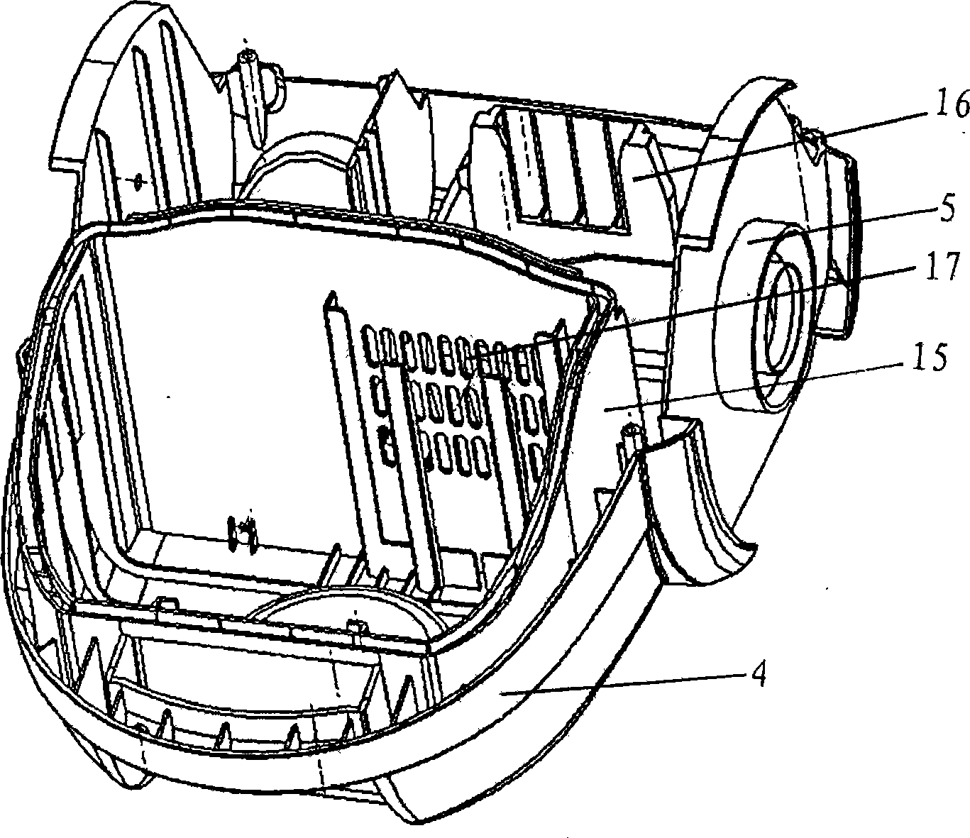
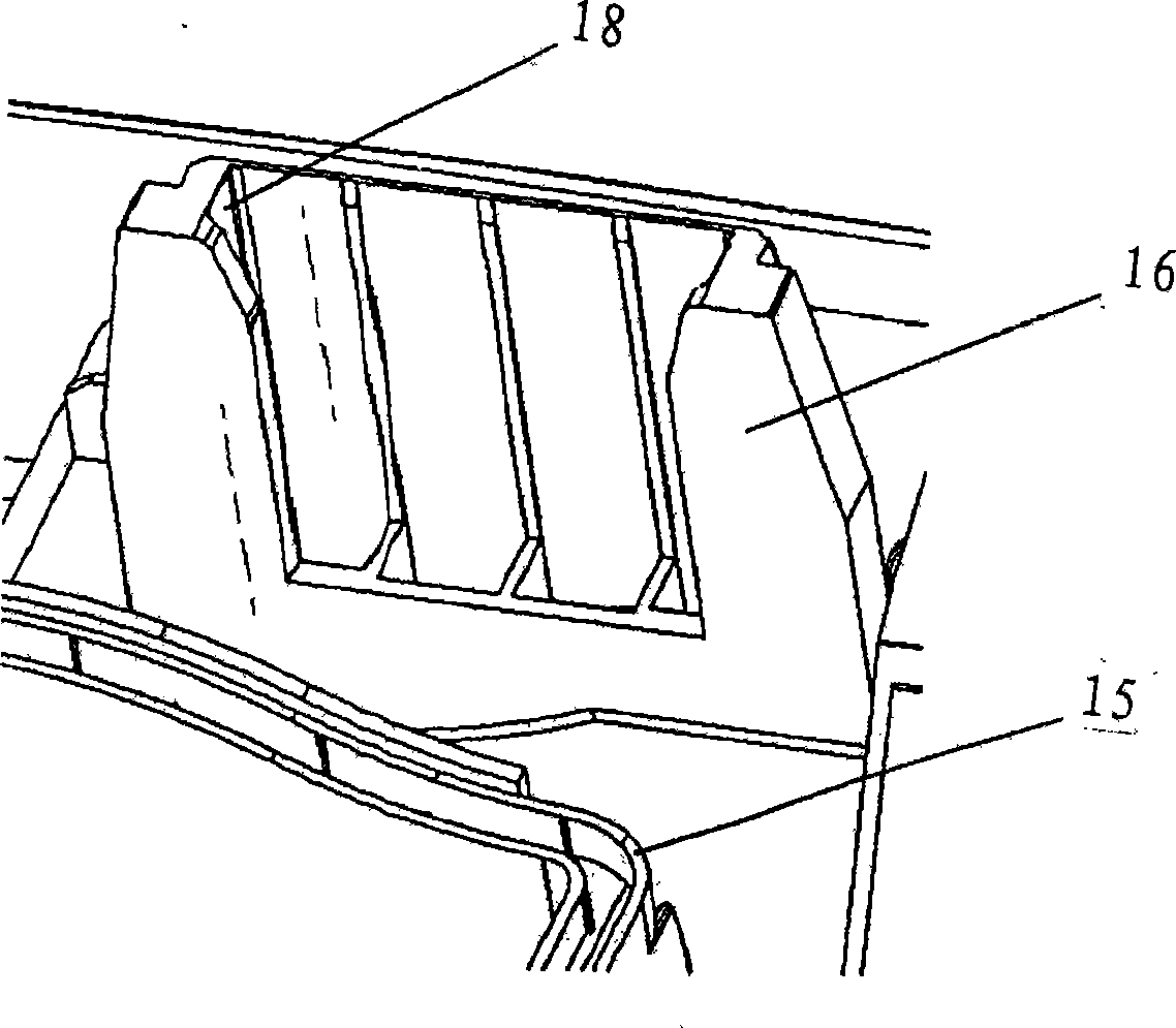
[0028] The specific embodiment of the present invention will be further described in conjunction with the accompanying drawings. Figure 4 It is a structural diagram of part of the bottom shell of the body of the vacuum cleaner involved in the present invention. As shown in the figure, the vacuum cleaner motor fixing structure involved in the present invention includes a motor fixing frame 16, the motor is placed in the motor fixing frame 16, and springs 19 are arranged between the motor fixing frame 16 and the two sides of the motor in contact. Small grooves 18 are respectively arranged on both sides of the motor fixing frame 16, and a spring 19 is respectively arranged in the two small grooves 18. One end of the inner spring 19 of the small groove 18 of the motor fixing frame 16 is against the inner side of the small groove 18, and the other end is against the side end of the motor.


PUM


Abstract

The invention relates to a motor fixing structure of a dust collector, which includes a motor fixing frame; the motor is arranged in the motor fixing frame; a spring is arranged between the motor fixing frame and two sides of the contacted motor. The two sides of the motor fixing frame are respectively provided with small grooves; each small groove is provided with a spring. One ends of the springs in the small grooves of the motor fixing frame are against with the inner sides of the small grooves and the other ends are against with the side end of the motor. The motor fixing structure of the dust collector changes the fixing ribs at the two sides of the motor into spring structures, thereby avoiding the deformation of a fixing piece, leading the motor to be firmly fixed in the fixing frame and ensuring the dust collector to be normally operated and used for a long period of time.

Description

technical field [0001] The invention relates to the shell structure of the vacuum cleaner, in particular to the fixing structure of the motor of the vacuum cleaner. [0002] Instructions. Background technique [0003] The vacuum cleaner is a household appliance for indoor cleaning and hygiene, which is used to remove dust from the ground, carpets, walls, furniture and various gaps. The vacuum cleaner mainly consists of a suction device and a suction pipeline. 0 The suction device is set in the body, including a motor and a fan. The suction pipeline includes a suction head and a suction pipe. The suction head has a suction port opening downwards and communicates with the dust box in the body through the suction pipe. The motor drives the impeller of the fan to rotate at high speed, exhausts the air in the vacuum cleaner, forms an instantaneous vacuum in the vacuum cleaner, and forms a relatively high negative pressure difference with the outside atmosphere. Under the effe...

Claims


Application Information

Patent Timeline
IPC IPC(8): A47L9/22
Inventor 于松
Owner LG ELECTRONICS (TIANJIN) APPLIANCES CO LTD
Features
  • R&D
  • Intellectual Property
  • Life Sciences
  • Materials
  • Tech Scout
  • Unparalleled Data Quality
  • Higher Quality Content
  • 60% Fewer Hallucinations
Learn More