
Micro chip type sum frequency laser
A microchip laser and laser gain technology, applied in the laser field, can solve the problems such as longitudinal mode frequency drift
Patent Information
- Authority / Receiving Office
- CN · China
- Patent Type
- Applications(China)
- Current Assignee / Owner
- Publication Date
- 2009-03-11
- Estimated Expiration
- Not applicable · inactive patent
Smart Images
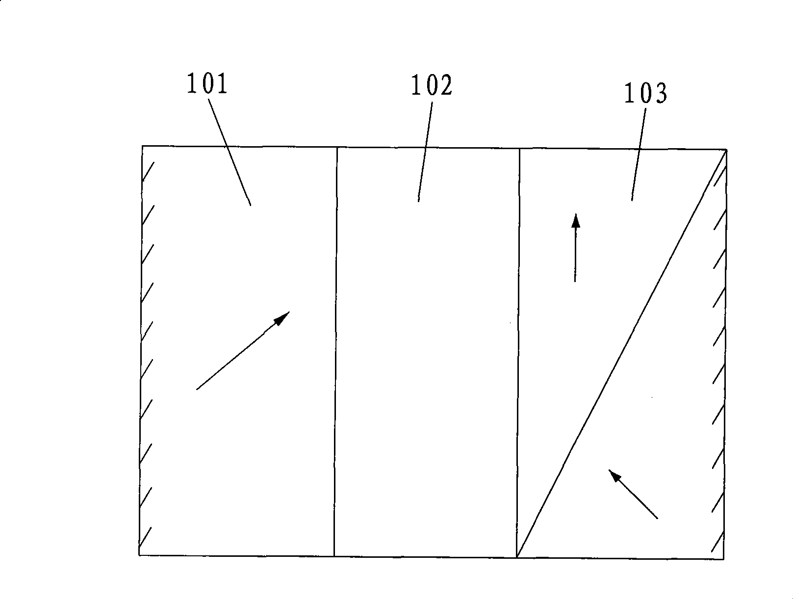
Figure 1 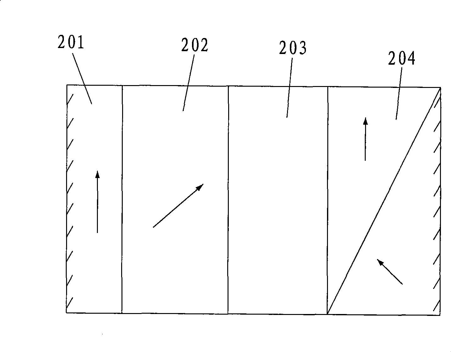
Figure 2 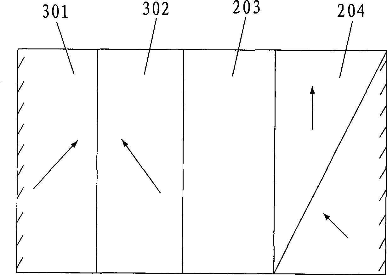
Figure 3
Abstract
Description
technical field
[0001] The invention relates to the field of lasers, in particular to a wide-temperature microchip laser that eliminates the influence of the Lyot filter on the laser output wavelength and has stable power. Background technique
[0002] In the field of lasers, the transmission curve of the Lyot filter has Sin 2 A function of λ, that is, the transmittance changes periodically with wavelength, and the transmittance is 1 only at certain wavelength points. If the Lyot filter is used in the laser cavity or the laser cavity has the structure of the Lyot filter, only the laser mode of a certain frequency can vibrate. With the change of ambient temperature, the laser cavity length will change, and its longitudinal mode frequency will therefore drift. If the frequency coverage of the gain curve is more than one transmission cycle of the Lyot filter, such as several cycles or dozens of cycles, then as the laser cavity length changes, the frequency will shift to the r...
Examples
Embodiment approach 1
[0025] like figure 2 As shown, the optical element structure is a 1 / 4 wave plate 201, a frequency doubling crystal 202, a laser gain medium crystal 203 and a polarizer 204 arranged in sequence. Both sides of the 1 / 4 wave plate 201 and the polarizer 204 are reflective film to form a laser resonator.
[0026] The laser first passes through the frequency doubling crystal. Due to the birefringence effect of the frequency doubling crystal, the o and e light of the laser will have a phase delay, and the laser will pass through the 1 / 4 wave plate twice, which is equivalent to a 1 / 2 wave plate, so it is quite Since the directions of the o and e lights are reversed, the phase delay of the o and e lights is eliminated when they pass through the frequency doubling crystal again. Therefore, this structure can eliminate the effect of Lyot filter on wavelength selection caused by temperature-induced cavity length change.
Embodiment approach 2
[0028] like image 3 As shown, the optical element structure is a composite of two frequency doubling crystals 301 and 302, a laser gain medium crystal 203 and a polarizer 204, which are arranged in sequence with their optical axes perpendicular to each other and of equal thickness. The two sides of the frequency doubling crystal 301 and the polarizer 204 are coated with a reflective film to form a laser resonant cavity.
[0029] In the same way, two frequency-doubling crystals with the optical axes perpendicular to each other and of equal thickness are combined. After the laser passes through the combination of the pair of frequency-doubling crystals, the phase delays cancel each other out. Therefore, the wave plate effect of the crystal can also be eliminated.
Embodiment approach 3
[0031] same image 3 Similarly, the optical element structure described is a composite of frequency-doubling crystals and other crystals arranged in sequence, a laser gain medium crystal 203 and a polarizer 204 . The frequency doubling crystal and the polarizer 204 are coated with reflective films on both sides to form a laser resonant cavity.
[0032] For the composite of frequency doubling crystal and other crystals, the principle is the same as the combination of two frequency doubling crystals with mutually perpendicular optical axes and equal thickness. The key is to use other crystals to offset or form the phase delay of the frequency doubling crystal to the laser. Low order full wave plate or 1 / 2 wave plate. Therefore, the purpose of wide temperature can also be achieved.