Synchronous expansion mechanism for foldable inflating expansion solar cell paddles

A technology for solar cells and deployment mechanisms, applied in the directions of light radiation generators, generators/motors, photovoltaic power generation, etc., can solve the problems of solar cell sailboard size and power limitations, low synchronous deployment performance, and poor reliability, etc. The effect of the source system is simple and reliable, light weight and low cost

Inactive Publication Date: 2009-03-11
HARBIN INST OF TECH
View PDF1 Cites 36 Cited by
  • Summary
  • Abstract
  • Description
  • Claims
  • Application Information

AI Technical Summary

Problems solved by technology

[0003] The purpose of the present invention is to provide a synchronous unfolding mechanism for folding and inflatable solar panels to solve the problem that the existing solar panel deployment mechanism is driven by a spring, and the synchronization mechanism adopts a rope linkage mechanism.
With the increase of the number of solar panels, the degree of asynchrony gradually increases, and the reliability is poor, which leads to the limitation of the size and power of the solar panel, as well as the problems of large volume, heavy weight, high cost, and low performance of synchronous deployment.

Method used


Image

  • Synchronous expansion mechanism for foldable inflating expansion solar cell paddles
  • Synchronous expansion mechanism for foldable inflating expansion solar cell paddles
  • Synchronous expansion mechanism for foldable inflating expansion solar cell paddles

Examples


specific Embodiment approach 1

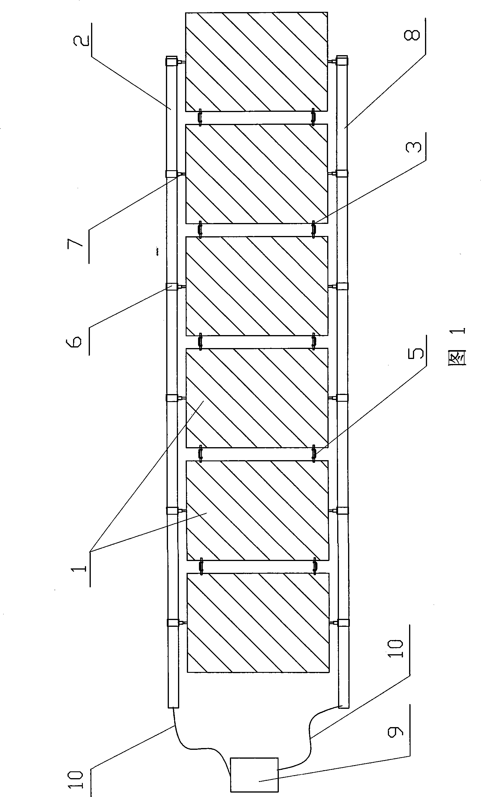
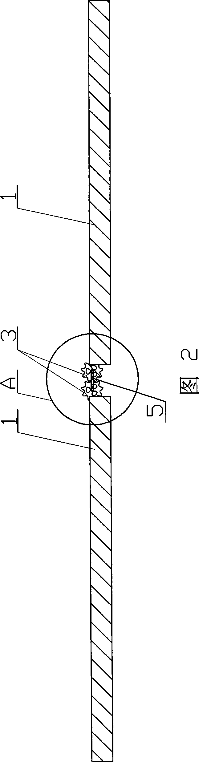
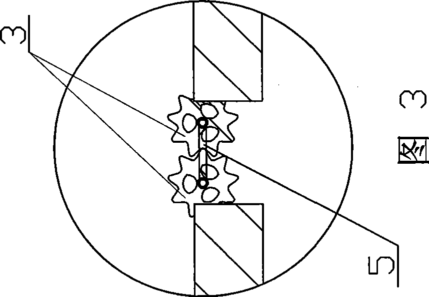
[0007] Specific Embodiment 1: This embodiment is described in conjunction with Fig. 1 to Fig. 5. The synchronous deployment mechanism of this embodiment includes a plurality of solar battery sail panels 1, and the plurality of solar battery sail panels 1 are arranged in a row; the synchronous deployment The mechanism also includes a driving inflation tube 2, a plurality of pairs of gears 3, a plurality of connecting rods 5, a plurality of connecting ring columns 6, a plurality of connecting shafts 7, an inflation guide tube 8, an air source 9 and two conduits 10; The tube 2 and the inflation guide tube 8 are arranged above and below a plurality of solar battery sails 1 respectively, and a pair of mutually meshing gears 3 are respectively provided at the upper end and the lower end between two adjacent solar battery sails 1 to ensure that the When the size of the gear 3 is not too large, it can be folded efficiently. If high synchronization accuracy is required, the number of te...

specific Embodiment approach 2

[0008] Specific Embodiment 2: This embodiment is described in conjunction with FIG. 1. The connection ring column 6 set on the driving inflatable tube 2 and the inflatable guide tube 8 of this embodiment corresponds to the middle position of the solar battery sail panel 1, ensuring that the solar battery Windsurfing 1 is launched smoothly. Other components and connections are the same as those in the first embodiment.

specific Embodiment approach 3

[0009] Specific embodiment three: This embodiment is described in conjunction with Fig. 1, Fig. 4 and Fig. 5. Each connecting ring column 6 of this embodiment is composed of a ring sleeve 6-1 and a guide column 6-2, and the ring sleeve 6-1 The outer wall of the guide post 6-2 is fixedly connected to one end of the guide post 6-2, and one end of the guide post 6-2 is provided with an axial inner shoulder hole 6-3 communicating with the ring sleeve 6-1, and the connecting shaft 7 is mounted on the guide In the axial inner shoulder hole 6-3 of the column 6-2, the inner end of the connecting shaft 7 is a spherical head 6-4, and the spherical head 6-4 of the connecting shaft 7 is axially limited by the shoulder end face, and connected The ring column 6 and the connecting shaft 7 can rotate mutually. When installing, the connecting shaft 7 is penetrated by the connecting ring column 6 and welded to the solar cell sail 1. The outer end surface of the connecting shaft 7 is connected to...


PUM


Abstract

The invention discloses a synchronous deployment mechanism for a folding inflating expansion type solar panel substrate, and the synchronous deployment mechanism relates to a solar panel substrate deployment mechanism. Aimed at solving the problems of the prior solar panel substrate deployment mechanism that the reliability is bad, the volume is large, the weight is heavy, the cost is high, and the synchronous deployment performance is low, an inflation driving pipe and an inflation guiding pipe are arranged above and below the solar panel substrate, a pair of mutually meshed gears is respectively arranged at the upper end and the lower end, both of which are positioned between the two adjacent solar panel substrates, the two ends of a connecting rod are sleeved on the gear shafts of each pair of gears, each pair of gears is connected with the adjacent solar panel substrate, a connecting ring pillar sleeved on the inflation driving pipe is fixedly connected with the inflation driving pipe, a connecting ring pillar sleeved on the inflation guiding pipe is glidingly matched with the inflation guiding pipe, connecting shafts are arranged in the connecting ring pillars, the external end faces of the connecting shafts are fixedly connected with the solar panel substrates, and a gas source is communicated with the inflation driving pipe and the inflation guiding pipe. The invention has the advantages of simple structure, light weight, high folding efficiency, good reliability and synchronous deployment.

Description

technical field [0001] The invention relates to a solar cell sail panel unfolding mechanism. Background technique [0002] The invention patent application with publication number CN 1696012A, date of publication is November 16, 2005, and titled "solar battery sail panel unfolding mechanism" discloses that the solar battery sail panel is driven by a spring, and the synchronization mechanism adopts a rope linkage mechanism. With the solar panel with the above structure, as the number of solar panel increases, the degree of asynchrony increases gradually, and the reliability is poor, which leads to the limitation of the size and power of the solar panel. In addition, there are also the problems of large volume, heavy weight, high cost, and low performance of simultaneous deployment. Contents of the invention [0003] The purpose of the present invention is to provide a synchronous unfolding mechanism for a foldable, inflatable and unfoldable solar panel to solve the problem...

Claims


Application Information

Patent Timeline
Patent Type & Authority Applications(China)
IPC IPC(8): H02N6/00B64G1/44H02S30/20
CPCY02E10/50
Inventor 谭惠丰杜振勇苗常青王长国林国昌王超
Owner HARBIN INST OF TECH
Why Eureka
Try Eureka