Dynamo-electric defeatherer head

A technology for hair removal and electric driving, which is applied to hair or scalp washing devices, clothing, hairdressing equipment, etc., and can solve the problem that when the driving mechanism in the body of the electric hair removal device drives the rotating cylinder of the head of the electric hair removal device to rotate At this time, the movable blade of the plucking assembly on the rotating cylinder and its base clamping part rotate around the arcuate shaft together, so that the movable blade is squeezed by the base clamping part on the narrower side of the arcuate shaft to perform clamping action. However, the loosening action is performed on the side of the bow-shaped shaft that is gradually wider, that is, the side of the bow-shaped shaft that is narrowed by the adjacent movable blades is clamped closer to each other, the speed of hair removal and the degree of hair removal are not satisfactory, and the hair is clamped. Insufficient clamping force and other problems, achieve the effect of good appearance consistency, avoid pain and discomfort, and reduce lateral vibration

Inactive Publication Date: 2009-03-18
SUPERMAN GROUP
View PDF2 Cites 2 Cited by
  • Summary
  • Abstract
  • Description
  • Claims
  • Application Information

AI Technical Summary

Problems solved by technology

However, in this patented technology, the rotating cylinder of the head of the electric epilator still uses the arcuate shaft as the rotating shaft passing through it. When the driving mechanism in the body of the electric epilator drives the rotating cylinder When the body rotates, the movable blade of the plucking assembly on the rotating cylinder and its base clamping part rotate around the arcuate shaft together, so that the movable blade is squeezed and clamped by the base clamping part on the narrower side of the arcuate shaft action, and the loosening action is done on the side of the bow-shaped shaft that is gradually widening, that is, the hair is clamped and pulled out by the adjace

Method used


Image

  • Dynamo-electric defeatherer head
  • Dynamo-electric defeatherer head
  • Dynamo-electric defeatherer head

Examples


Embodiment Construction

[0022] The technical solution of the present invention will be further described below in conjunction with the accompanying drawings.

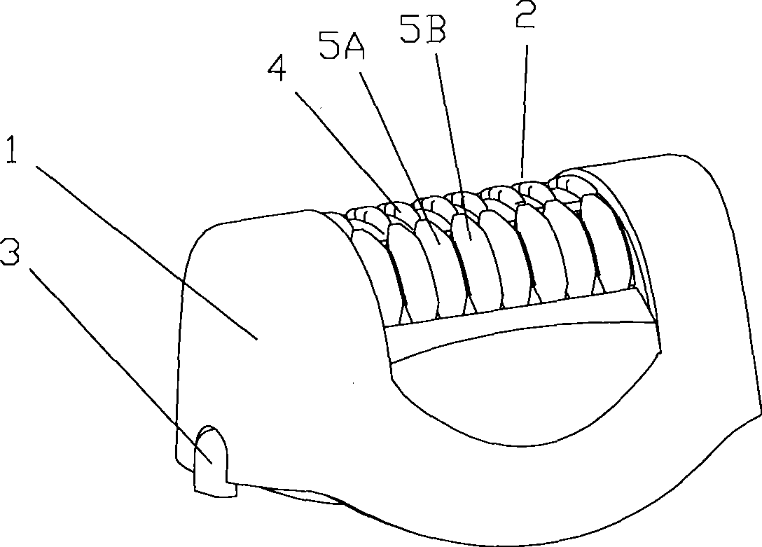
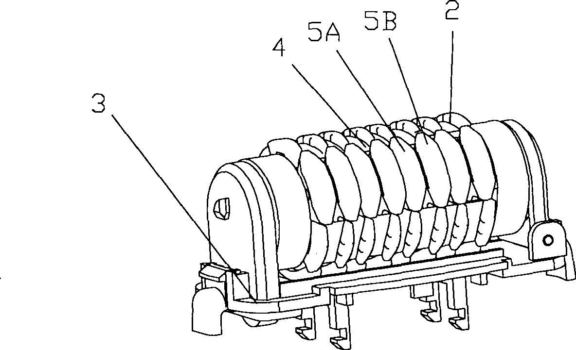
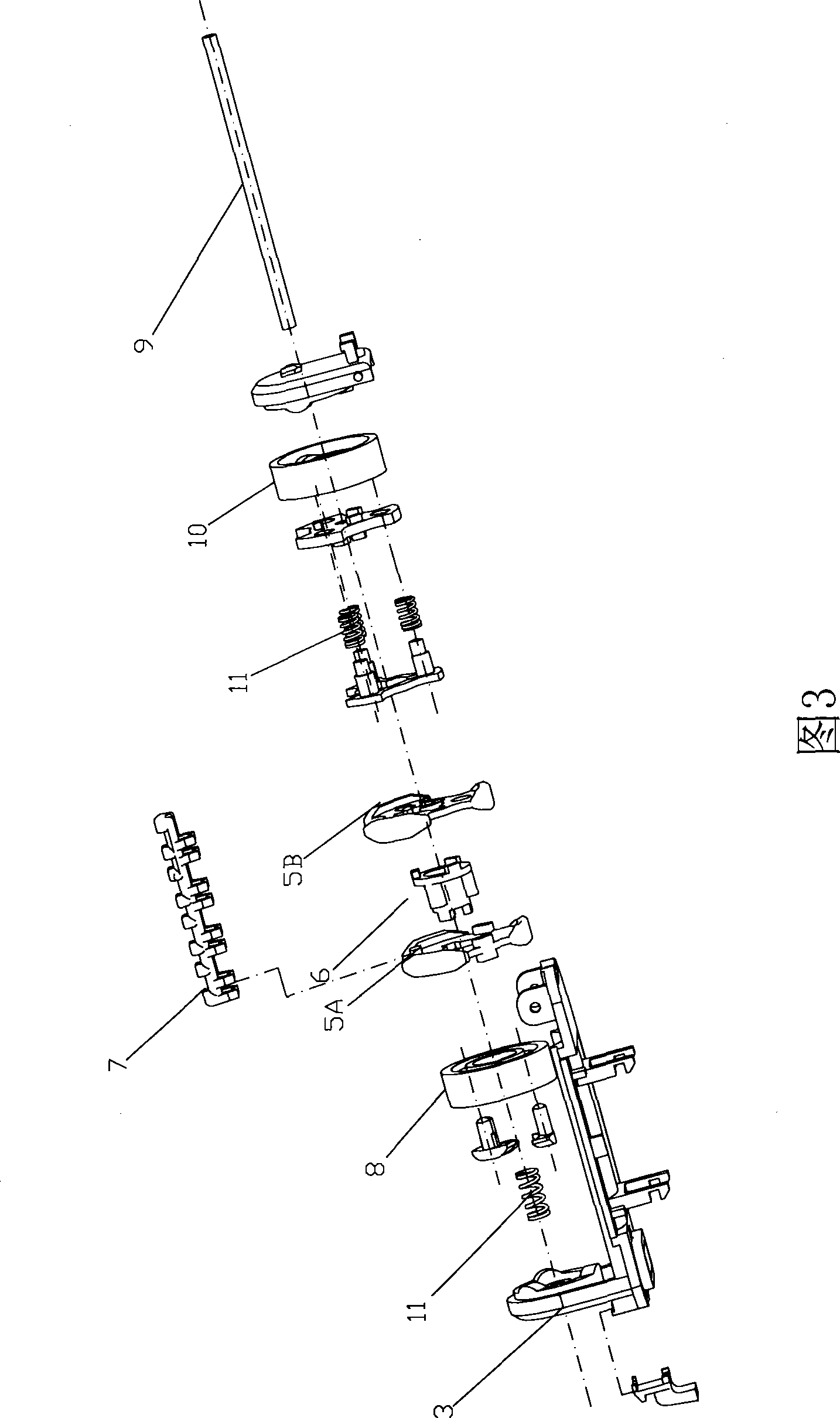
[0023] figure 1 Shows the three-dimensional appearance view of the head of the electric hair plucker of the present invention, figure 2 A perspective view showing the structure of the head of the electric hair plucker of the present invention after removing the mesh head. From figure 1 with figure 2 It can be seen that the head of the electric epilator of the present invention includes a mesh head 1, a rotating cylinder 2 and a supporting base 3. The head of the electric epilator can be connected to the body of the epilator (not shown) through the supporting base 3. Assembly and disassembly connection. The rotating cylinder 2 is provided with a plurality of plucking components 4, and further from the three-dimensional exploded view of the partial structure of the head of the electric hair pluck of the present invention shown in FIG. The eleme...


PUM


Abstract

An electric defeatherer head belongs to the individual nursing appliance and aims at overcoming the technical deficiencies that in the prior art, a movable cutter blade of a hair removal component is lack of gripping force; the electric defeatherer head comprises a net head, a rotating cylinder and a support base, wherein, the rotating cylinder is provided with at least one hair removal component which is composed of a nipper element that touches the skin when in hair removal and a base component; the electric defeatherer head is characterized in that the rotating cylinder is provided with a straight shaft which goes through vertically and is provided with the hair removal component that is made of plastics and rotates around the straight shaft. The technical proposal adopts the longitudinal straight shaft as a core shaft of the rotating cylinder which is arranged straightly; after being tried out, the electric defeatherer is proved to further improve the contacting comfortableness of the users when the head of the electric defeatherer is touched with the skin; the user feels that the comfortableness is improved in the hair removal process; the speed for removing the hair is accelerated and the cleanliness of hair removal is enhanced; after being removed the hair, the trier generally reports the situation that the pain caused by removing hair is weaken, and the comfortableness is enhanced after hair removal.

Description

Technical field [0001] The present invention relates to a personal care appliance, in particular to an electric hair plucker head with a hair plucking component made of plastic that rotates around a straight axis to realize the plucking function. Background technique [0002] After electric shavers, electric hair clippers and other personal care appliances that are popular with customers, electric hair pluckers have gradually become the new favorite of personal care home appliances on the market. The application number is 200420072190.X and the authorized announcement number is CN2722646Y. The invention patent discloses a technical solution for an electric hair plucker. After research, the applicant developed a new technical solution to improve the above-mentioned patented technical solution, and recently (June 9, 2007) Applied for the patent of "Electric Epilator" (Patent Application Number: 200720110533.0). The head of the electric epilator involved in this patent application i...

Claims


Application Information

Patent Timeline
IPC IPC(8): A45D26/00
Inventor 应平祥
Owner SUPERMAN GROUP
Why Eureka
Try Eureka