
Tool conveying mechanical arm

A manipulator and workpiece technology, applied in the field of workpiece conveying manipulators, can solve problems such as low transmission efficiency and complex transmission structure, and achieve the effects of reducing weight, simplifying transmission structure, and avoiding strong impact.

Inactive Publication Date: 2009-03-18
YANGZHOU METALLURGICAL MACHINERY
View PDF0 Cites 8 Cited by
  • Summary
  • Abstract
  • Description
  • Claims
  • Application Information

AI Technical Summary

Problems solved by technology

The transmission structure of the above-mentioned workpiece conveying manipulator is complicated, and the transmission efficiency is low, so it is only suitable for light-load and low-speed occasions

Method used


Image

  • Tool conveying mechanical arm
  • Tool conveying mechanical arm
  • Tool conveying mechanical arm

Examples


Embodiment Construction

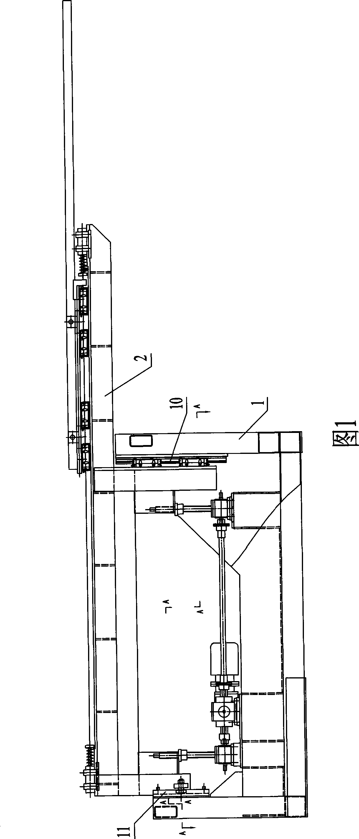
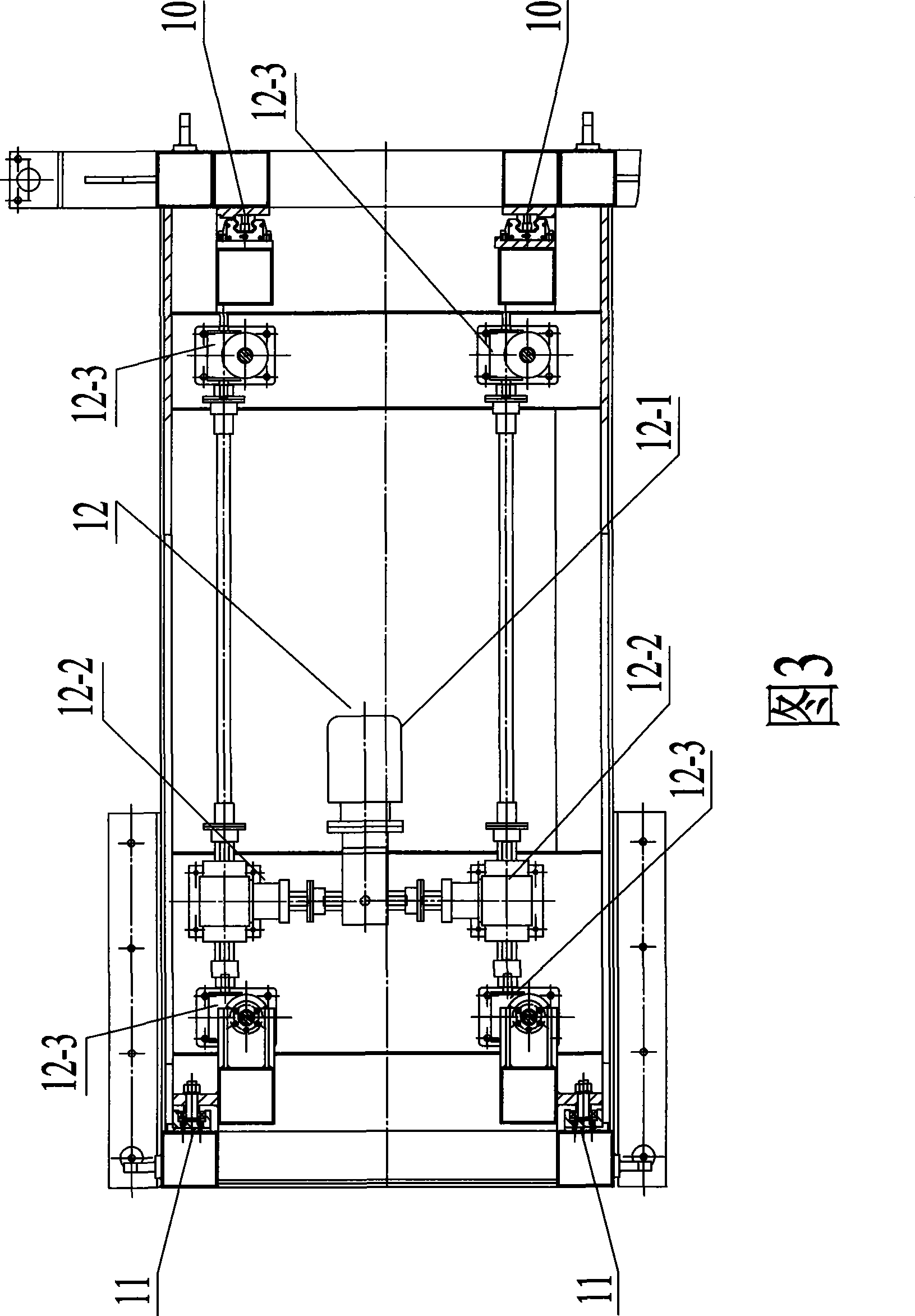
[0019] As shown in FIG. 1 , the workpiece conveying manipulator includes a first frame 1 and a second frame 2 , and the second frame 2 is connected to the first frame 1 .

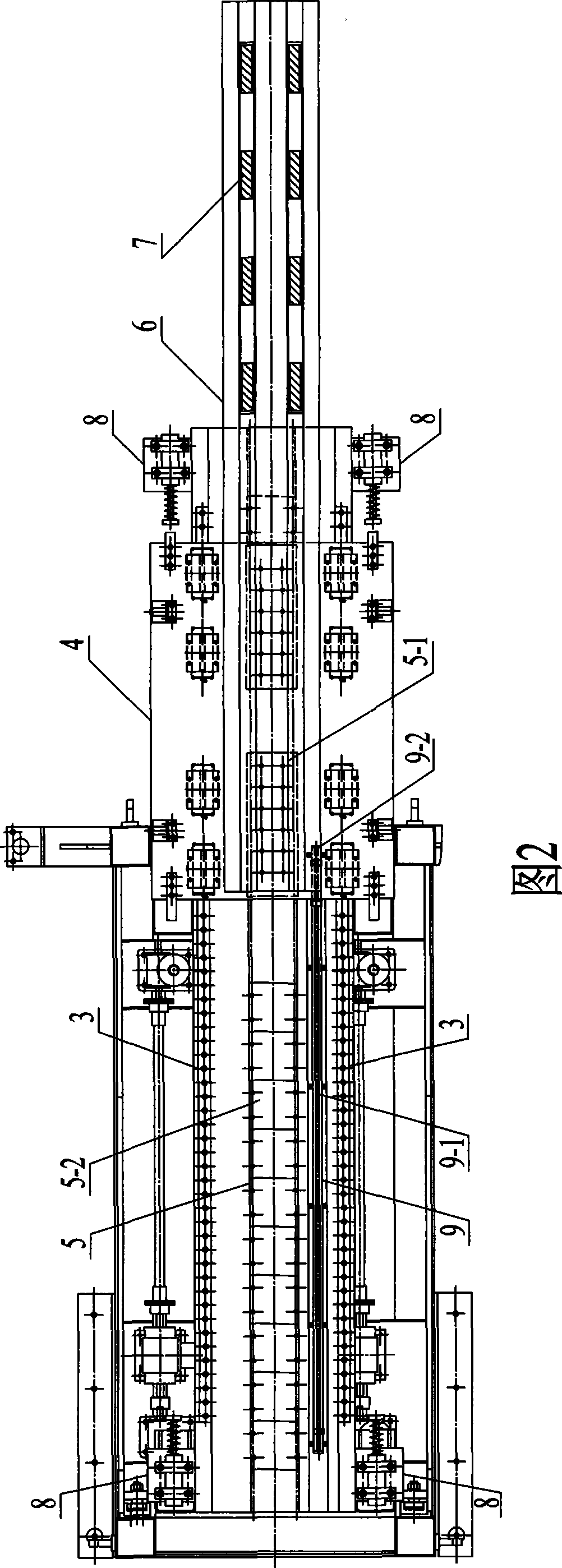
[0020] As shown in Figure 2, two parallel horizontal linear guide rails 3 are connected on the upper surface of the second frame 2, and a manipulator 4 is connected on the above-mentioned horizontal linear guide rail 3, and the manipulator 4 can move along the horizontal linear guide rail 3. Slide back and forth.

[0021] It also includes a linear motor 5 that can drive the manipulator 4 to reciprocate along the horizontal linear guide rail 3 . The primary 5 - 1 of the linear motor 5 is connected to the lower surface of the manipulator 4 , and the secondary 5 - 2 of the linear motor 5 is connected to the upper surface of the second frame 2 .

[0022] A receiving hand 6 is connected on the manipulator 4, and the clamping device 7 for fixing the workpiece is installed on the upper surface of the receiving ha...


PUM


Abstract

The invention discloses a workpiece conveying manipulator used for forging mechanical automatic equipment in the technical field of forging mechanical automatic equipment. The workpiece conveying manipulator comprises a frame, a linear motor, a horizontal linear guide way, a manipulator and a take-up hand, wherein, the manipulator is arranged on the upper surface of the frame; the linear guide way is connected with the frame in a sliding way through the horizontal linear guide way; the linear motor is arranged between the manipulator and the frame so as to drive the manipulator to reciprocate along the horizontal linear guide way; and the take-up hand is connected on the manipulator. The workpiece conveying manipulator has the advantages of simple driving structure and high driving efficiency, and is applicable to burden high-speed occasions.

Description

technical field [0001] The invention belongs to the technical field of forging machinery automation equipment, and in particular relates to a workpiece conveying manipulator used for forging machinery automation equipment. Background technique [0002] The workpiece conveying manipulator used on the existing forging machinery is usually driven by a servo motor or a stepping motor to drive a rolling screw, a synchronous toothed belt, a rack and pinion and other actuators to complete the conveying of the workpiece. The transmission structure of the above-mentioned workpiece conveying manipulator is complicated, and the transmission efficiency is low, so it is only suitable for occasions with light load and low speed. Contents of the invention [0003] The technical problem to be solved by the present invention is to provide a workpiece conveying manipulator with simple transmission structure and high transmission efficiency, which can be applied to heavy-load and high-speed ...

Claims


Application Information

Patent Timeline
Patent Type & Authority Applications(China)
IPC IPC(8): B25J3/04B25J15/00B25J15/06
Inventor 程洪波孙成建贾鲁宁
Owner YANGZHOU METALLURGICAL MACHINERY
Learn More