Rainwater underground gathering apparatus

A collection device and rainwater collection technology, applied in water supply devices, drinking water devices, general water supply conservation, etc., can solve problems such as low efficiency, complex structure, poor water quality, etc., and achieve low cost, full collection, and low cost effects

Inactive Publication Date: 2009-03-18
GUANGDONG LIANSU TECH INDAL
View PDF2 Cites 3 Cited by
  • Summary
  • Abstract
  • Description
  • Claims
  • Application Information

AI Technical Summary

Problems solved by technology

[0005] The purpose of the present invention is to overcome the existing rainwater collection method inefficiency, poor water quality, and the shortcomings of complex structure and adopt the rainwater underground collection method, which is a large-scale rainwater collection scheme that is simple, easy to install, and low in cost

Method used


Image

  • Rainwater underground gathering apparatus
  • Rainwater underground gathering apparatus
  • Rainwater underground gathering apparatus

Examples


Embodiment 1

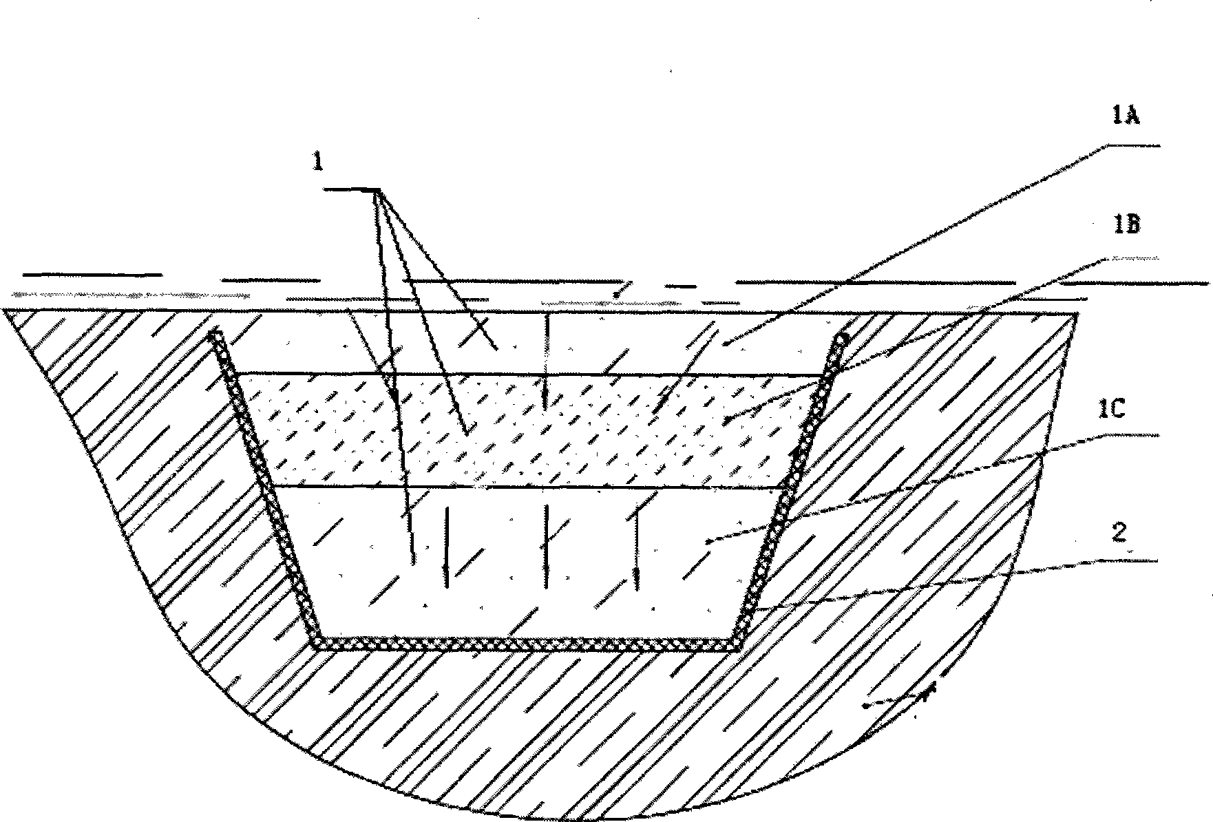
[0029] The structural schematic diagram of embodiment one is as figure 1 As shown, it includes a filter layer 1 and a rainwater collection pipe 2 under the filter layer 1. The rainwater collection pipe 2 is an open pipe, and the uppermost layer of the filter layer 1 is a sandstone layer 1A, and the middle includes a fine sand layer 1B. The lowest layer is the coarse stone layer 1C.

[0030] When the surface water flows through the sandstone layer 1A, due to its own gravity, the water will seep down along the gap between the sandstones, and when it flows through the fine sand layer 1B, because the gap between the fine sand is relatively small, it has Filtering function, all the rainwater is filtered, and all the impurities inside are left in the fine sand. The relatively clear rainwater enters the coarse stone layer 1C, where the gap is large and the water flow resistance is small. The rainwater collection pipe 2 is set during installation There is a certain slope, and the rai...

Embodiment 2

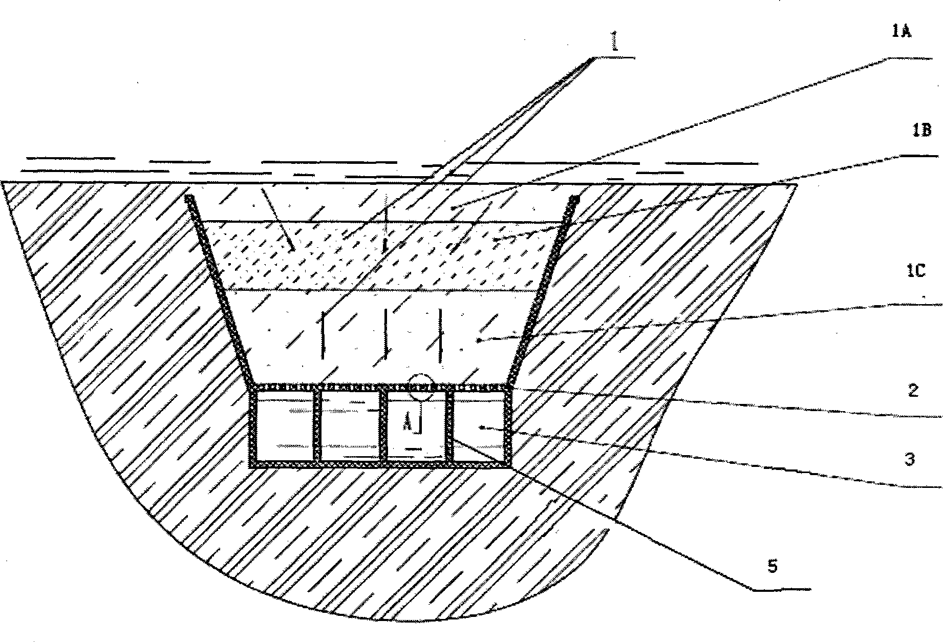
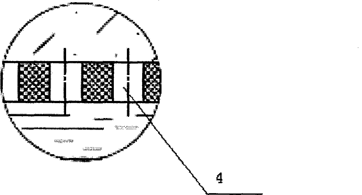
[0032] The structural schematic diagram of embodiment two is as figure 2 As shown, it includes a filter layer 1 and a rainwater collection pipe 2 under the filter layer 1. The rainwater collection pipe 2 is an open pipe, and the uppermost layer of the filter layer 1 is a sandstone layer 1A, and the middle includes a fine sand layer 1B. The lowest layer is the coarse stone layer 1C; the rainwater collection pipe 2 is provided with a through pipe 3, and the through pipe 3 communicates with the rainwater collection pipe 2 through the collection pipe guide hole 4, and the through pipe reinforcement rib 5 is also arranged in the through pipe to support the upper Rainwater collection pipe 2.

[0033] When the surface water flows through the sandstone layer 1A, due to its own gravity, the water will permeate down along the gap between the sandstones. When it flows through the fine sand layer 1B, because the gap between the sandstones is relatively small, the water itself has the abi...

Embodiment 3

[0036] The structural schematic diagram of embodiment three is as Figure 4 As shown, it includes a filter layer 1 and a rainwater collection pipe 2 under the filter layer 1. The rainwater collection pipe 2 is an open pipe, and the uppermost layer of the filter layer 1 is a sandstone layer 1A, and the middle includes a fine sand layer 1B. The lowest layer is the coarse stone layer 1C; the rainwater collection pipe 2 is provided with a through pipe 3, and the through pipe 3 communicates with the rainwater collection pipe 2 through the collection pipe guide hole 4, and the through pipe reinforcement rib 5 is also arranged in the through pipe to support the upper Rainwater collection pipe 2. The difference from the second embodiment is that a filter medium 7 is also provided in the through pipe 3, and in order to ensure the effect of the filter medium, a filter membrane or activated carbon can be selected.

[0037] When the surface water flows through the sandstone layer 1A, due...


PUM


Abstract

The invention provides a rainwater underground collection device, which comprises a filter layer and a rainwater collection pipe which is arranged under the filter layer, wherein the rainwater collection pipe is an open pipeline; a topmost layer of the filter layer is a sand stone layer; the middle of the filter layer comprises a fine sand layer; and an undermost layer of the filter layer is a coarse stone layer. The rainwater underground collection device utilizes the reasonable layer arrangement of sand stone, fine stone and coarse stone to filter rainwater. The topmost sand stone layer can accelerate the rainwater infiltration and perform first-step filtration; the fine sand layer in the middle has obvious filtration effect, and filters most of impurities in the rainwater; and the undermost coarse stone layer keeps the filtered rainwater smooth because of large intermediate gap and little resistance to water flow. As filter materials are all common low-cost materials in daily life, the device has the advantage of low cost and is suitable for large-scale application.

Description

technical field [0001] The invention relates to a water conservancy engineering pipeline device, in particular to an underground rainwater collection device. technical background [0002] my country's water resources are seriously deficient, the per capita share is less than one-third of the world's average, and the northern region is less than one-eighth of the world's average. An effective rainwater harvesting system is the need for sustainable development of the country's economic construction. Most of the existing rainwater collection methods use surface collection and diversion trenches. The rainwater collected in this way has many impurities and poor water quality, and it needs to be treated for a long time before it can be used. [0003] In the literature search of the prior art, the patent application number is ZL03138439.0, and the patent name is: The patent literature of rainwater collection and irrigation system discloses a rainwater collection device, including a...

Claims


Application Information

Patent Timeline
IPC IPC(8): E03B3/02B01D35/027
CPCY02A20/108
Inventor 杨卫
Owner GUANGDONG LIANSU TECH INDAL
Why Eureka
Try Eureka