Vehicle transverse swinging parking device

A parking device and yaw technology, which is applied in the field of simple parking devices for vehicles, can solve the problems of high manufacturing cost, high cost, and heavy weight, and achieve the effects of simple and convenient installation and arrangement, low manufacturing cost, and light weight

Inactive Publication Date: 2009-03-18
CHONGQING UNIV
View PDF0 Cites 12 Cited by
  • Summary
  • Abstract
  • Description
  • Claims
  • Application Information

AI Technical Summary

Problems solved by technology

[0002] When the vehicle needs to be parked on the roadside, garage or parking lot with vehicles or obstacles in the front and rear, it is difficult to park in, drive out or park squarely due to the narrow space, especially unskilled drivers will find it very difficult to operate. It takes a long time, and if the operation is not done properly, there may be a scratching accident, causing unnecessary losses
In order to solve the above problems, there have been devices that can be quickly and easily parked in various vehicles, but these devices are more complicated in structure and have little practical value.
For example: there is a car lateral movement mechanism, two sets of lateral movement mechanisms are respectively arranged on the horizontal frames of the two rear wheels, the hydraulic cylinder drives the mechanism to lift up and down, and the servo motor drives the vehicle to move laterally and swing. The mechanism is complicated and requires a hydraulic power source. The layout of the pipeline is inconvenient; a car lateral movement and swing device is equipped with two sets of devices at the front or rear of the car. The device is driven by a hydraulic cylinder to drive the lever to realize the lifting movement, and the motor drives the car to swing through the chain transmission mechanism. There is also a complicated mechanism. Problems such as inconvenient layout; a car lateral moving device sets four sets of moving devices on the front and rear axles close to the wheels, each moving device is driven up and down by a hydraulic cylinder, and driven laterally by a hydraulic motor, which has complex mechanisms and high costs , the problem of inconvenient layout; a car lateral movement transfer device, three or four sets of transfer devices are arranged on the chassis of the car, which are driven by hydraulic cylinders to lift up and down, and electric motors or hydraulic motors drive the runners through two sets of bevel gear transmission mechanisms , the mechanism is more complicated, and the above-mentioned problems also exist, and the mechanism is heavy, so it is difficult to actually apply it to a car; it can be seen from the above that the existing simple parking device generally has a complex structure and requires complex pipelines and lines. , high manufacturing cost, heavy weight, does not conform to the development trend of light weight and energy saving and emission reduction of modern vehicles, and is not suitable for small and medium-sized vehicles such as cars

Method used


Image

  • Vehicle transverse swinging parking device
  • Vehicle transverse swinging parking device
  • Vehicle transverse swinging parking device

Examples


Embodiment 1

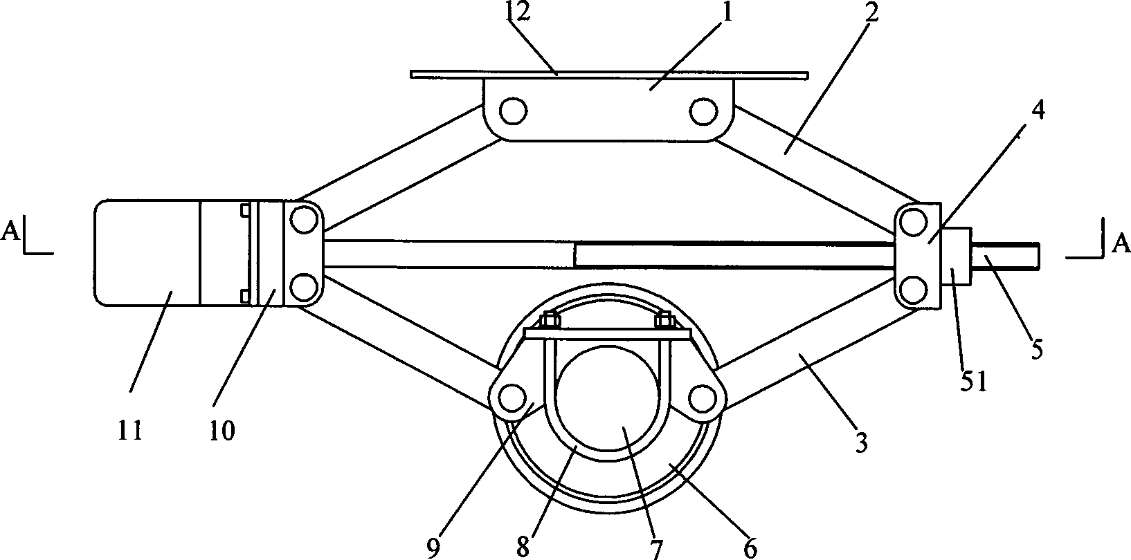
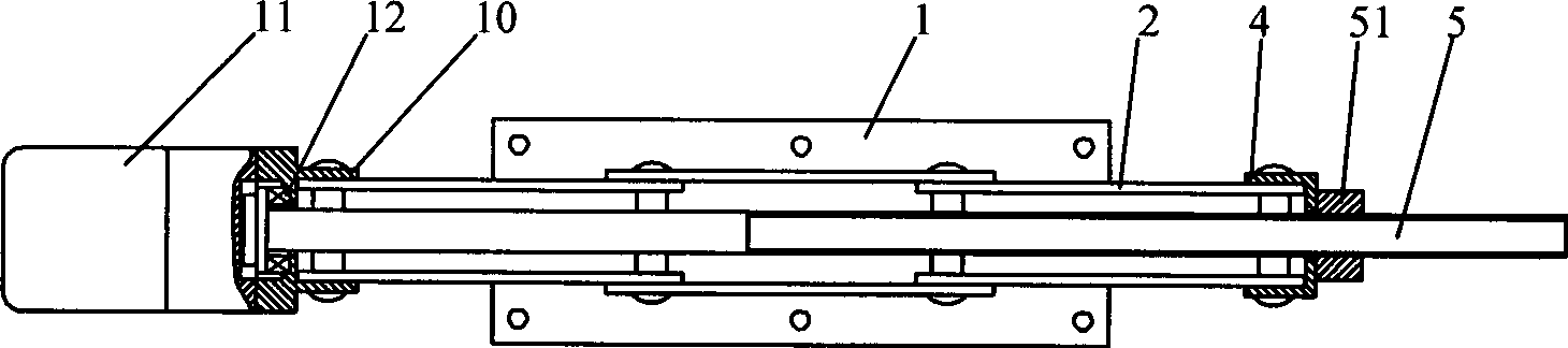
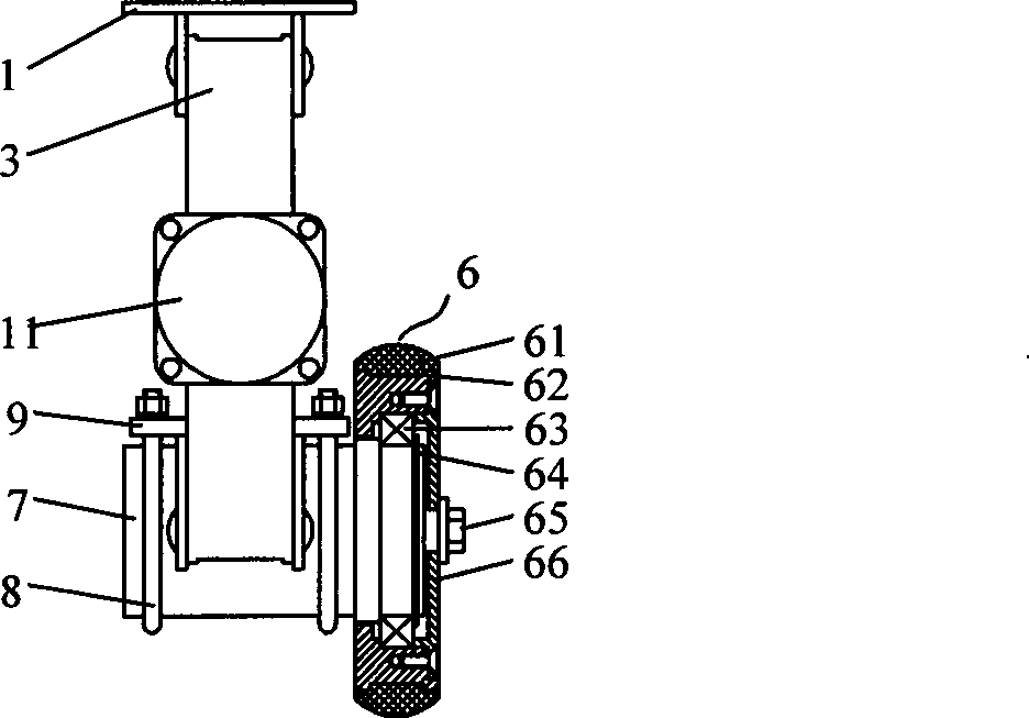
[0023] figure 1 It is a structural schematic diagram of Embodiment 1 of the present invention, figure 2 for figure 1 Sectional view along A-A direction, image 3 It is a schematic diagram of the lateral drive wheel assembly of the present invention, as shown in the figure: the vehicle sway parking device of the present embodiment includes a lifting mechanism and a swaying mechanism, and the lifting mechanism includes a lifting power device 11, a screw mandrel 5, and a screw mandrel 5 screwed on Nut 51, two upper struts 2 and two lower struts 3, the lifting power device 11 can drive the screw mandrel 5 to rotate; two upper struts 2 and two lower struts 3 move with the screw mandrel 5 and the nut 51 respectively The pair consists of an upper plane four-bar mechanism and a lower plane four-bar mechanism;

[0024] The yaw mechanism includes a yaw power device 7 and a lateral drive wheel 6, the yaw power device 7 can drive the lateral drive wheel 6 to rotate, and the lower end ...

Embodiment 2

[0028] Figure 4 It is a structural schematic diagram of Embodiment 2 of the present invention, as shown in the figure: the difference between this embodiment and Embodiment 1 is: a second lateral drive wheel 13 is arranged in parallel with the lateral drive wheel 6 on the lower support 9, and the second lateral drive wheel 13 The wheel 13 is arranged on the lower support 9 through the rotational cooperation of the rotating shaft 14 and the second radial rolling bearing 15 . Because the second transverse driving wheel 13 and the transverse driving wheel 6 are arranged side by side laterally, the left and right balance can be kept after the rear of the vehicle is raised, and no tilting to the left or right can take place.


PUM


Abstract

The invention discloses a vehicle transverse swinging stopping device, which comprises a lifting mechanism and a transverse swinging mechanism, wherein the lifting mechanism comprises a lifting power unit, screw mandrels, nuts screwed on the screw mandrel, two upper stay bars and two lower stay bars; the two upper stay bars and the two lower stay bars respectively take the screw mandrels and the nuts as movable pairs to form an upper plane four-bar mechanism and a lower plane four-bar mechanism; and the transverse swinging mechanism comprises a transverse swinging power unit and a transverse driving wheel. The vehicle transverse swinging stopping device adopts a movable pair type plane four-bar mechanism which is combined with a transverse driving wheel structure to complete lift and sideslip of the tail of a vehicle, is convenient to put straight the tail of the vehicle under the condition of parking, does not require arrangement of complex pipelines and lines, is simple and convenient to arrange, has low manufacturing cost and light weight, accords with the development trends of light weight, energy saving and emission reduction of the modern vehicle, and is suitable for parking of middle-size and small-size vehicles such as sedans, etc. in a narrow place.

Description

technical field [0001] The invention relates to a simple parking device for vehicles, in particular to a vehicle sway parking device. Background technique [0002] When the vehicle needs to be parked on the roadside, garage or parking lot with vehicles or obstacles in the front and rear, it is difficult to park in, drive out or park squarely due to the narrow space, especially unskilled drivers will find it very difficult to operate. It takes a long time, and if the operation is not done properly, a rubbing accident may occur, causing unnecessary losses. For solving the above problems, there have been devices that can be quickly and easily parked that various vehicles carry, but these device structures are all more complicated and have little practical value. For example: there is a car lateral movement mechanism, two sets of lateral movement mechanisms are respectively arranged on the horizontal frames of the two rear wheels, the hydraulic cylinder drives the mechanism to ...

Claims


Application Information

Patent Timeline
Patent Type & Authority Applications(China)
IPC IPC(8): E04H6/42
Inventor 刘振军余猛进蒋维
Owner CHONGQING UNIV
Why Eureka
Try Eureka