Method realizing adjustment of laser frequency difference and laser thereof

A frequency difference and laser technology, applied in the field of lasers, can solve the problems of complex system, increased installation and adjustment, difficulty, etc., and achieve the effect of easy pump installation and adjustment

Active Publication Date: 2009-03-18
FUZHOU PHOTOP QPTICS CO LTD
View PDF0 Cites 12 Cited by
  • Summary
  • Abstract
  • Description
  • Claims
  • Application Information

AI Technical Summary

Problems solved by technology

These solutions make the system complex, increase the difficulty of assembly and adjustment, and affect the stability

Method used


Image

  • Method realizing adjustment of laser frequency difference and laser thereof
  • Method realizing adjustment of laser frequency difference and laser thereof
  • Method realizing adjustment of laser frequency difference and laser thereof

Examples


no. 1 approach

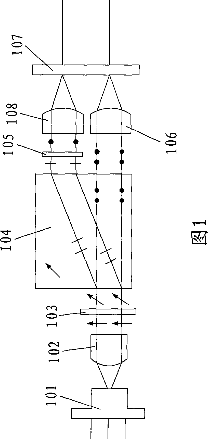
[0039] As shown in Figure 1, the emitted light beam of an LD laser pump source 101 passes through a collimating lens 102 and a 1 / 2 wave plate 103 and then enters a Walk-off crystal 104. The first light beam emitted by the Walk-off crystal 104 It enters the single longitudinal mode laser cavity 107 directly after passing through the first focusing lens 106; the second beam emitted from the Walk-off crystal 104 passes through another 1 / 2 wave plate 105 and then enters the single longitudinal mode laser after passing through the second focusing lens 108 Cavities 107.

[0040] By rotating the wave plate 103, there is a certain difference in the pump power on both sides to adjust the frequency difference. The 1 / 2 wave plate 105 restores the pump light to the same polarization again. The advantage of this structure is that the pump light is the light emitted by the same LD, which eliminates system errors as much as possible.

no. 2 approach

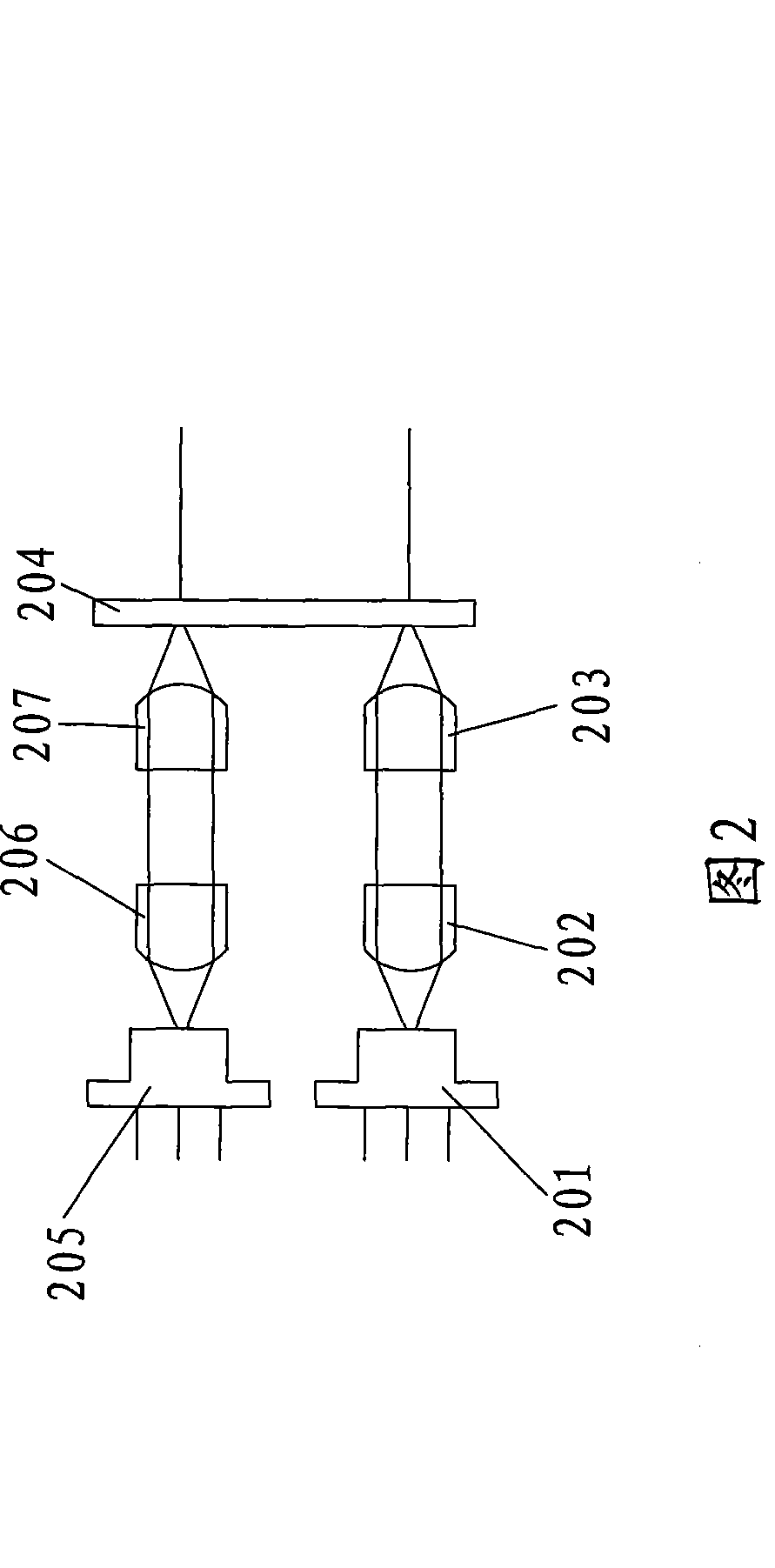
[0042] As shown in FIG. 2, the output beam of the first LD laser pump source 201 passes through the first collimating lens 202 and the first focusing lens 203 and then enters the single longitudinal mode laser cavity 204; the output of the second LD laser pump source 205 The light beam enters the single longitudinal mode laser cavity 204 after passing through the second collimating lens 206 and the second focusing lens 207.

[0043] In this structure, the requirements for two laser pumps are high, and the two pump power supplies need to be precisely controlled. Its advantages are: the beam splitting prism can be omitted, the structure is simpler, and the frequency difference can be adjusted directly by adjusting the currents of the two LD laser pumping sources, which makes the adjustment very convenient.

no. 3 approach

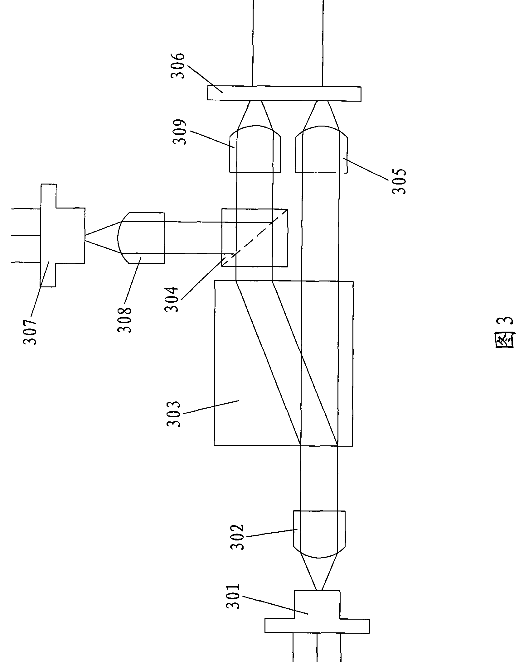
[0045]As shown in Fig. 3, the emitted light beam of an LD laser pump source 301 enters a Walk-off crystal 303 after passing through a collimating lens 302, and the first light beam emitted by the Walk-off crystal 303 is directly incident on the focusing lens 305. Single longitudinal mode laser cavity 306; the second beam emitted by the Walk-off crystal 303 passes through a PBS prism 304, and the output beam of another LD laser pump source 307 perpendicular to the second beam emitted by the Walk-off crystal 303 passes through a The collimating lens 308 is also incident on the PBS prism 304, and the output beam of the PBS prism 304 is incident on the single longitudinal mode laser cavity 107 after passing through the focusing lens 309.

[0046] The advantage of this structure is that the adjustment of the frequency difference of the output laser is more convenient and the adjustment range is wider.


PUM


Abstract

The invention relates to the field of lasers, in particular to a method for achieving the adjustment of laser frequency difference and a single longitudinal mode microchip laser thereof. The method for achieving the adjustment of laser frequency difference comprises leading pump power to be basically the same through two different pump point-source light source pump lasers, and getting needed laser frequency difference through adjusting pump power difference. The invention simultaneously discloses four single longitudinal mode microchip lasers whose frequency difference can be adjusted through using the method. With the technical proposal, the invention has the advantages of miniaturization and easy installation and adjustment of LD pump, which is a novel method for achieving the adjustment of laser frequency difference and a single longitudinal mode microchip laser whose frequency difference can be adjusted.

Description

Technical field [0001] The invention relates to the field of lasers, in particular to a method for realizing the adjustable laser frequency difference and its single longitudinal mode microchip laser. Background technique [0002] Orthogonal polarization dual-frequency lasers play an important role in precision measurement applications. The principle is to change the internal beam properties of the orthogonal polarization dual-frequency laser through the measured object, such as changes in the number of frequencies (longitudinal modes) and frequency differences. Some physical quantities can be measured by changing the polarization characteristics of light, and changing the competition intensity of modes. For example, displacement measurement based on the competition of two polarizations of frequency-splitting lasers, displacement measurement based on the feedback of two-polarizations of frequency-splitting lasers, phase delay measurement of waveplates that directly use waveplates...

Claims


Application Information

Patent Timeline
Patent Type & Authority Applications(China)
IPC IPC(8): H01S3/102H01S3/106H01S3/0941
Inventor 吴砺邱英卢秀爱陈卫民凌吉武
Owner FUZHOU PHOTOP QPTICS CO LTD
Why Eureka
Try Eureka