Apparatus and method for the detection of the focused position of an optical system, and ophthalmological treatment apparatus

An optical system and focus position technology, applied in ophthalmic medical and/or diagnostic equipment, devices for controlling focus position, especially focus depth, and focus depth devices, can solve the problems of not implementing focus control, etc.

Active Publication Date: 2009-03-18
ALCON INC
View PDF9 Cites 13 Cited by
  • Summary
  • Abstract
  • Description
  • Claims
  • Application Information

AI Technical Summary

Problems solved by technology

No focus control is ex

Method used


Image

  • Apparatus and method for the detection of the focused position of an optical system, and ophthalmological treatment apparatus
  • Apparatus and method for the detection of the focused position of an optical system, and ophthalmological treatment apparatus
  • Apparatus and method for the detection of the focused position of an optical system, and ophthalmological treatment apparatus

Examples


Embodiment Construction

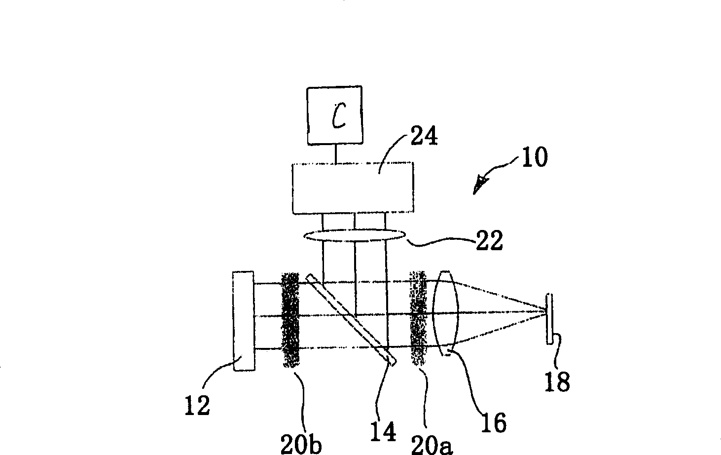
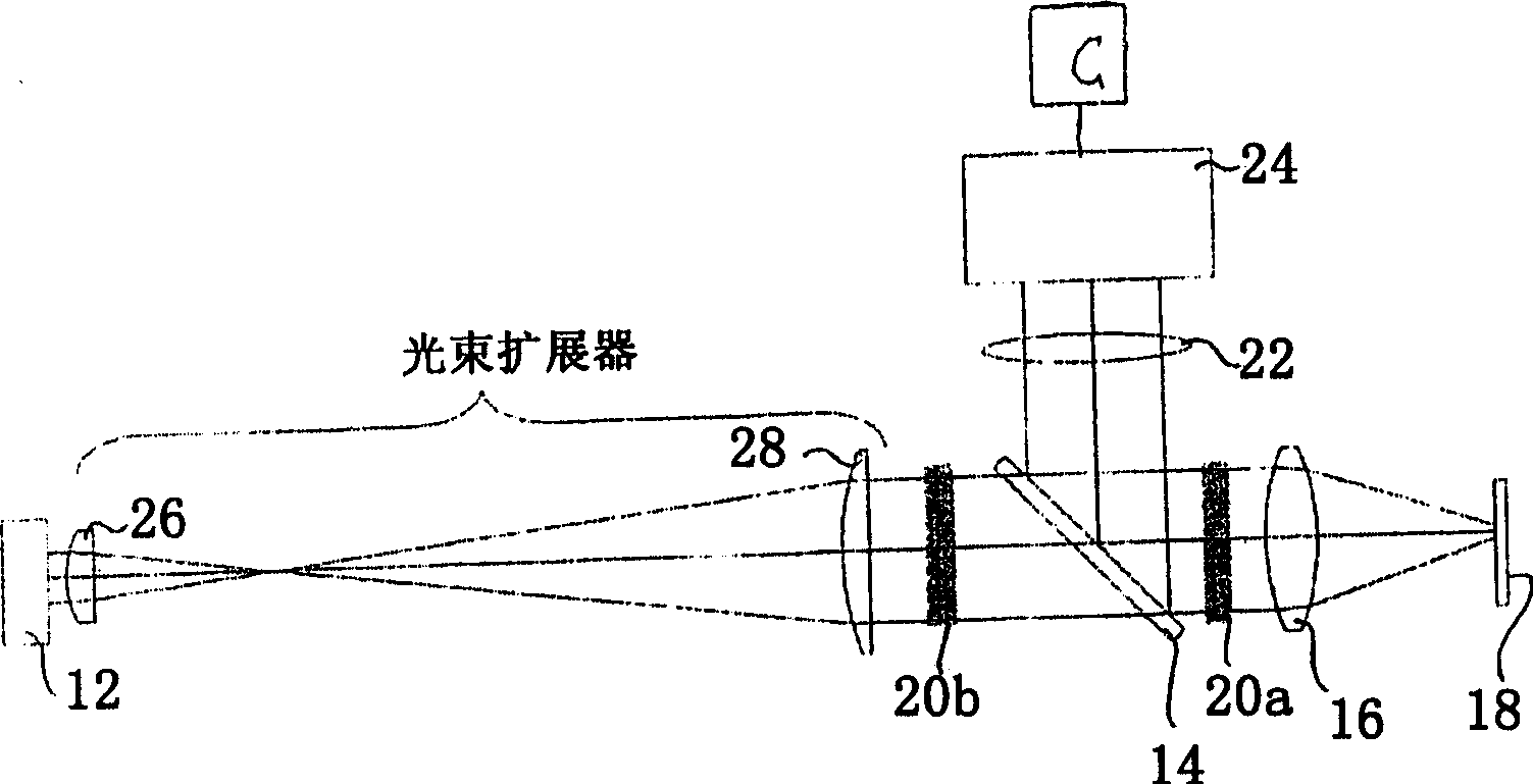
[0029] according to figure 1, the optical system 10 has a light source 12 which can be a laser (eg fs-laser) or an LED or the like. Radiation emitted by light source 12 passes through output mirror 14 and is focused onto plane 18 by focusing imaging system 16 . The focused imaging system 16 is diagrammatically represented in the figure by only a single lens. Typically the focus imaging system 16 has multiple lenses, one or more of which can be moved for setting and changing focus. Such optical imaging systems are known.

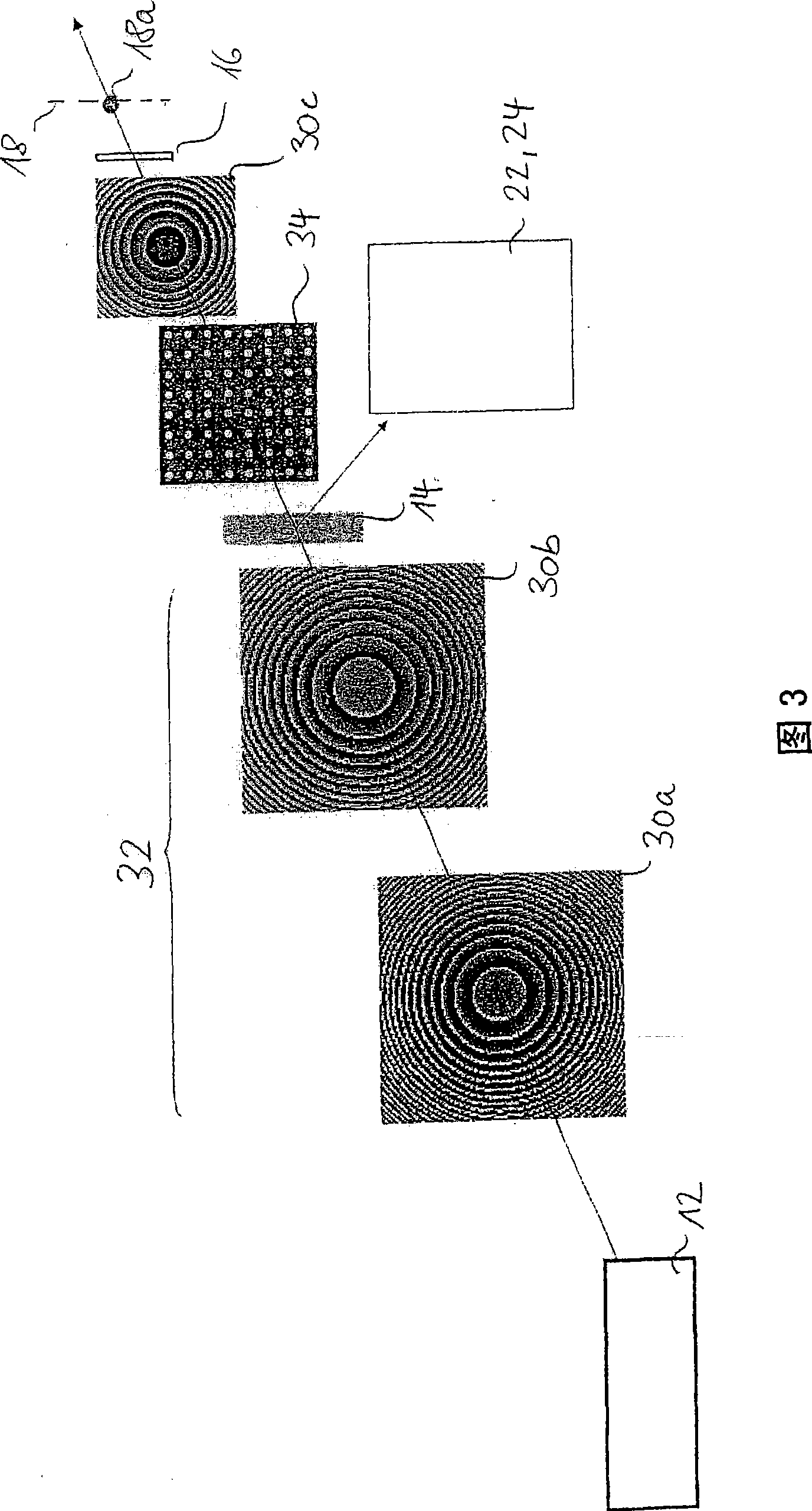
[0030] figure 1 , optical elements described in more detail hereinafter may be selectively placed at areas (points) indicated by reference numerals 20a and 20b. Examples of such optical elements are optical elements 34 and 36 shown in FIGS. 3 and 4 .

[0031] Radiation reflected by reflective surface 18 passes through optical imaging system 16 and, as will be described in more detail below, applicable optical elements disposed in region 20a, to output mi...


PUM


Abstract

Disclosed is an apparatus and a method for detecting the focused position of an optical system (10) comprising a radiation source (12), a focusing imaging system (16), an at least partially reflective surface (18) on the focus (18a), a digital camera (24) for recording an image that is reflected by said surface (18), a computer (C) for evaluating the image recorded by the camera (24), and an optical element (34; 36) in the beam path of the optical system (10) upstream of the focusing imaging system (16), the optical element (34; 36) influencing the image in accordance with the focused position.

Description

technical field [0001] The invention relates to a device and method for detecting the focus position of an optical system. In detail, the present invention relates to a device and method for detecting the depth of focus of an imaging optical system, and also relates to a device and method for controlling the position of focus, especially the depth of focus. Furthermore, the invention relates to an ophthalmic medical and / or diagnostic device using said device and / or said method. Background technique [0002] As far as the optical systems discussed here are concerned, specifically, the optical systems in question are imaging optical systems using light sources in material processing equipment, specifically, such as lasers and LEDs. In this context, material processing is also to be understood as the construction of materials in the microscale range, for example dielectrics such as biological tissue or metallic materials. In particular, the invention can be used in ophthalmic...

Claims


Application Information

Patent Timeline
IPC IPC(8): A61F9/01B23K26/04
CPCB23K26/0639B23K26/04B23K26/0656A61F2009/00855B23K26/0648A61F9/00827B23K26/032B23K26/0665A61F2009/00872B23K26/064B23K26/066G01J1/4257A61F9/008B23K26/046
Inventor 奥拉夫·柯特泰耳曼彼得·特里艾保
Owner ALCON INC
Why Eureka
Try Eureka