Capacitive sensing isolation using reversed biased diodes

A reverse bias, diode technology, used in weighing equipment using electrostatic balance, using electromagnetic/magnetic devices to transfer sensing components, measuring forces, etc., can solve problems such as affecting parasitic capacitance

Inactive Publication Date: 2009-03-18
TK HLDG
View PDF0 Cites 6 Cited by
  • Summary
  • Abstract
  • Description
  • Claims
  • Application Information

AI Technical Summary

Problems solved by technology

However, one disadvantage of using field effect transistors is that t

Method used


Image

  • Capacitive sensing isolation using reversed biased diodes
  • Capacitive sensing isolation using reversed biased diodes
  • Capacitive sensing isolation using reversed biased diodes

Examples


Embodiment Construction

[0014] Embodiments of the present invention will be described with reference to the accompanying drawings. In various embodiments of the invention described herein, like reference numerals refer to the same or similar parts throughout the drawings.

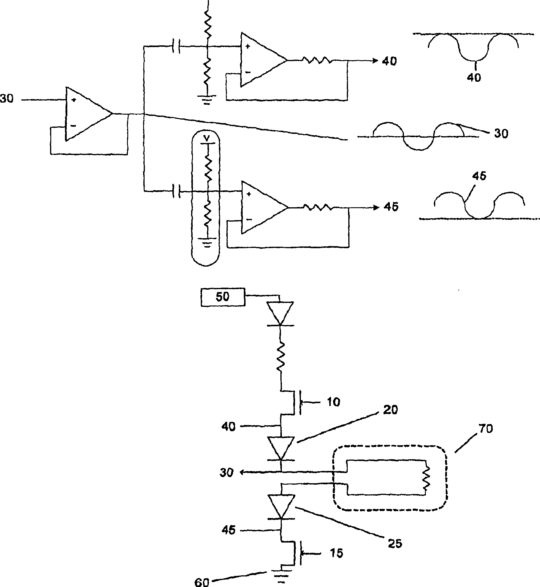
[0015] figure 1 A capacitive sensing system 1 according to one aspect of the invention is shown. Capacitive sensing signals for detecting occupants are generated by sensor / heating mat 70 . During sensing, the capacitive sensing system 1 ensures that the diodes 20, 25 do not conduct current by isolating the capacitive sensing signal 30 from the field effect transistors 10, 15 by utilizing the diodes 20, 25 and an applied reverse bias signal. . figure 1 The capacitive sensing signal 30 in is a sinusoidal signal, but can also be other time-varying signals. In the sense mode, a buffered sense signal with a DC offset smaller than the initial signal 40 is applied to the anode of the high-side diode 20; to the bias. Likewise, apply...


PUM


Abstract

The invention relates to a capacitive sensing isolation using reversed biased diodes. A capacitive sensor is provided. The capacitive sensor includes a sensor/heat pad for outputting a sensing signal, a first diode coupled to a first node of the sensor/heat pad, a second diode coupled to a second node of the sensor/heat pad, a first transistor coupled to the first diode and a second transistor coupled to the second diode. During a sensing mode, the first and second transistors are opened and a reverse-biased signal is applied to the first diode and the second diode so that the sensor/heat pad is isolated from the first and second transistors.

Description

[0001] Cross References to Related Applications [0002] This application claims priority to US Provisional Application Serial No. 60 / 762,125, filed January 26, 2006, which is hereby incorporated by reference. field of invention [0003] The present invention relates to passenger classification systems. Background technique [0004] A capacitive sensing system for a motor vehicle seat issues a time-varying voltage to a single sensing electrode and measures the load current from the sensing electrode to ground. The time-varying voltage can have many shapes, although the preferred shape is a sinusoidal signal with a frequency of about 50 KHz to about 150 KHz. This load current increases significantly when an adult passenger is in the seat and only slightly when a child is in the motor vehicle seat. [0005] Typically, capacitive sensing systems use the same element to both sense an occupant in a motor vehicle seat and to heat the motor vehicle seat. Typically, to switch bet...

Claims


Application Information

Patent Timeline
IPC IPC(8): G01D5/24G01D21/02B60R21/015B60N2/90
CPCB60R21/01532G01G19/4142G01D21/02B60R21/015G01G7/06G01L1/144G01D5/24B60N2/002B60R21/0154
Inventor S·科克P·马圭尔
Owner TK HLDG
Why Eureka
Try Eureka