Fixing/releasing auxiliary device for a wafer detection platform, the wafer detection platform and method therefor

A technology of auxiliary device and testing device, which is applied in the direction of measuring device casing, semiconductor/solid-state device testing/measurement, single semiconductor device testing, etc., and can solve the problem of inability of point measuring device to make correct conductive contact, lower output efficiency, and increase of carrying device Vacuum pump suction power and other issues, to improve detection efficiency and output yield, reduce wafer damage

Inactive Publication Date: 2009-03-25
CHROMA ELECTRONICS SHENZHEN
View PDF0 Cites 19 Cited by
  • Summary
  • Abstract
  • Description
  • Claims
  • Application Information

AI Technical Summary

Problems solved by technology

[0003] However, the above-mentioned warping phenomenon will prevent the spot measuring device from conducting the correct conductive contact to the height of each die, and the poor contact will make the detection impossible. Press the way to force the wafer to stick to the carrying surface; or increase the suction force of the vacuum pump connected to the carrying device to force the wafer to be strongly sucked to the carrying surface
[0004] However, regardless of manual pressure or strong suction, stress concentration may occur due to uneven force application, excessive pressure application, and some structural defects of the wafer to be tested, and the wafer to be tested may be broken.
Even when the vacuum pump is turned off to return the wafer to its warped state, the wafer will quickly return to its bent shape and cause fragmentation
In this way, not only the yield rate will decrease, but the cost will increase simultaneously; cleaning up the fragments will also delay the follow-up operations, which will significantly reduce the output efficiency

Method used


Image

  • Fixing/releasing auxiliary device for a wafer detection platform, the wafer detection platform and method therefor
  • Fixing/releasing auxiliary device for a wafer detection platform, the wafer detection platform and method therefor
  • Fixing/releasing auxiliary device for a wafer detection platform, the wafer detection platform and method therefor

Examples


no. 1 example

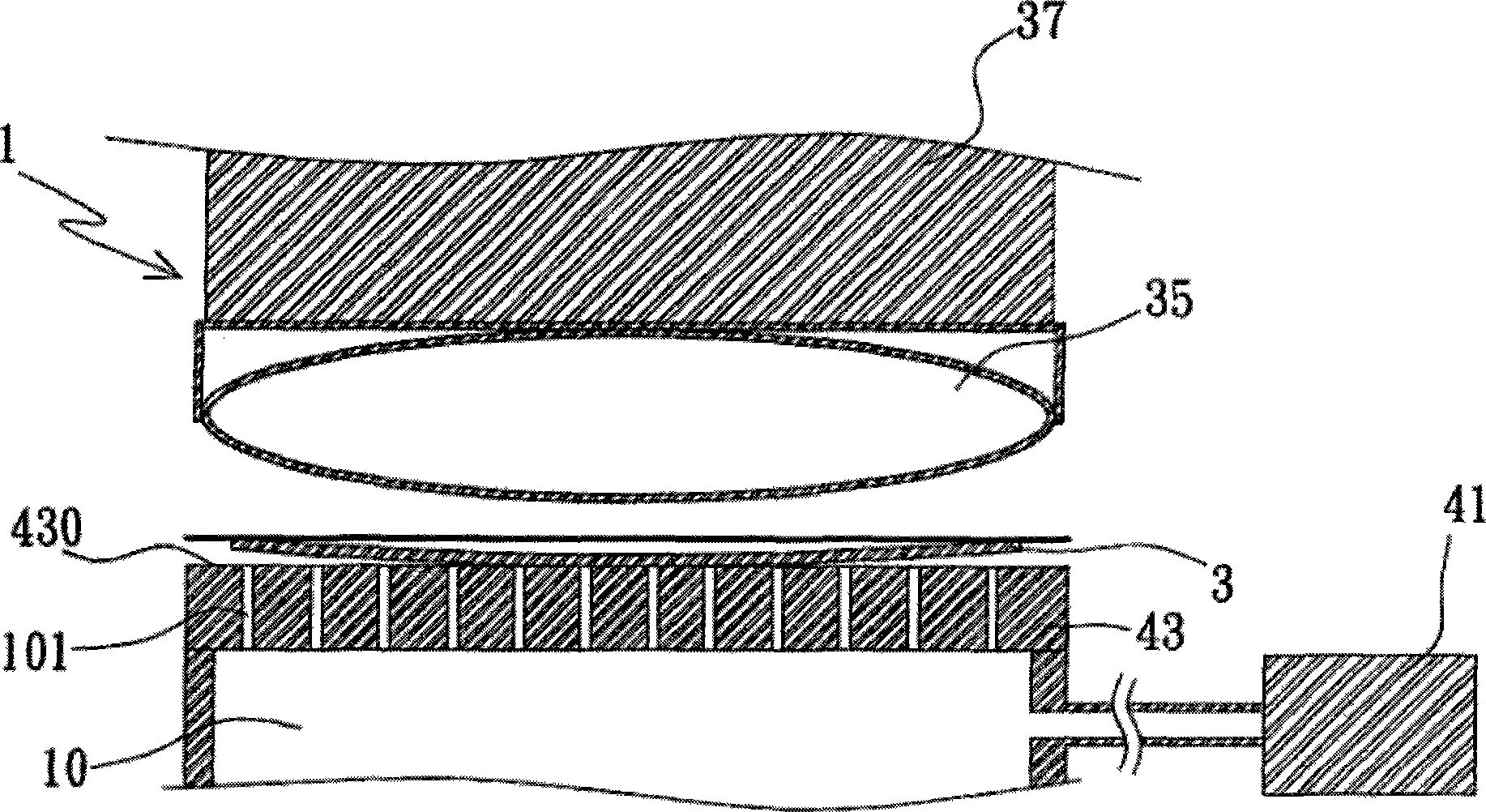
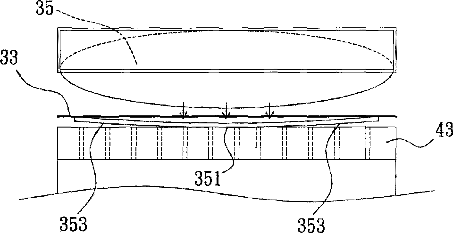
[0026] The present invention as figure 1 and figure 2 As shown, the fixing / releasing auxiliary device 1 utilizes a hollow sphere 35 whose central part 351 is obviously thicker than the peripheral part 353 as a flexible unit for applying pressure. reserve position, so Figure 6 In step 61 , after the wafer 3 to be tested is placed on the carrying surface 430 of the carrying device 43 , the ball 35 is moved to the top of the wafer 3 to be tested and gradually pressed down. Among them, the warpage of the wafer 3 to be tested is not radially symmetrical, but generally because the central part 351 is the lowest, it is close to a flat state when it is placed on the carrying surface 430; and at this time, the air holes 101 on the carrying surface 430 have been ventilated The connected exhaust pump 41 applies negative pressure.

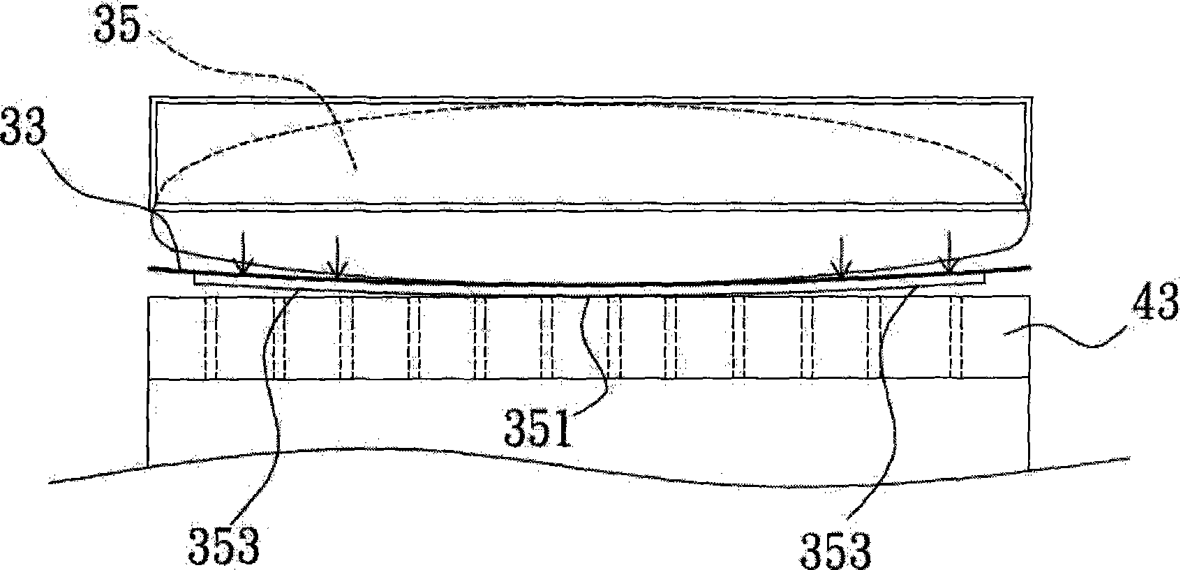
[0027] Therefore step 62 as Figure 1 to Figure 5 As shown, the central part 351 of the sphere 35 will preferentially press against the center of the wa...

no. 2 example

[0033] Of course, as those skilled in the art can easily understand, the flexible unit is not limited to hollow spheres, such as Figure 7 As shown in the second embodiment of this case, solid flexible members such as sponge 35' can also be used to make the thickness of the peripheral part 353' less than that of the central part 351', and when the wafer is finally flattened, the central part The thickness of 351' can be substantially equal to that of the peripheral part 353', which can meet the needs of this case, and exert pressure on the wafer surface to perform inspection operations.


PUM


Abstract

The invention discloses a fixing / releasing auxiliary device for wafer testing equipment, the testing equipment and a method thereof. The invention aims to help the testing equipment test a wafer to be tested, which is placed on the bearing surface of the bearing device of the testing equipment, by solving the problem that the uneven surface of the wafer stops the wafer from being successfully absorbed and fixed by air-pores on the bearing device. The method comprises the following steps: a set of mobile units are used for steadily pressing downwards a flexible material, so that the central part of the material, which is thicker than the peripheral part of the material, can come into contact with the central part of the wafer to be tested much earlier; and then the material is gradually pressed downwards so as to gradually flatten the whole piece of the wafer-the central part first and then the peripheral part-on the bearing surface. The invention provides an automatic operation mode, but also prevents the wafer to be tested from being broken or poor contact in the course of pressing, thereby enhancing the output yield and the output rate.

Description

technical field [0001] The invention relates to a fixing / releasing auxiliary device, in particular to a fixing / releasing auxiliary device for a wafer testing machine, the testing machine and a method. Background technique [0002] With the advancement of the technology industry, for example, the thickness of LED wafers has gradually decreased from the original 200 μm to less than 150 μm, resulting in uneven warpage of about 5 μm due to tension factors such as thermal stress during the manufacturing process. However, in the current existing testing process, the wafer to be tested is mostly placed on the carrying surface of the carrying device, and the carrying device is ventilated and connected to a vacuum pump, so that negative pressure is generated at the air holes on the carrying surface, and the adsorption is to be The wafer is measured, and the individual dies in the wafer are electrically contacted through the measuring device on the top, so as to light up each die and ...

Claims


Application Information

Patent Timeline
Patent Type & Authority Applications(China)
IPC IPC(8): H01L21/683H01L21/66G01R1/04G01R31/26
Inventor 曾一士陈正雄
Owner CHROMA ELECTRONICS SHENZHEN
Why Eureka
Try Eureka