High-speed main shaft electromagnetic type on-line dynamic balancing method

A high-speed spindle, electromagnetic technology, applied in static/dynamic balance testing, centering/balancing rotors, measuring devices, etc., can solve the problems of high speed and energy consumption, long response time, poor stability, etc., and achieve dynamic balance The effect of wide speed range, short response time, and simple and compact structure of the balance device

Inactive Publication Date: 2009-03-25
XI AN JIAOTONG UNIV
View PDF0 Cites 13 Cited by
  • Summary
  • Abstract
  • Description
  • Claims
  • Application Information

AI Technical Summary

Problems solved by technology

[0010] The purpose of the present invention is to solve the shortcomings of the existing online dynamic balance due to the need to generate a rotating electromagnetic field, which is limited by the rotational speed and excessive energy consumption, especially the indirect online dynamic balancing device and the hybrid online dynamic balancing device have complex structures and long response times And poor stability and other deficiencies, for the machine tool spindle with protruding end, it provides an electromagnetic online dynamic balancing method with quick response and convenient control

Method used


Image

  • High-speed main shaft electromagnetic type on-line dynamic balancing method
  • High-speed main shaft electromagnetic type on-line dynamic balancing method
  • High-speed main shaft electromagnetic type on-line dynamic balancing method

Examples


Embodiment Construction

[0027] The present invention will be further described in detail below with reference to the drawings and embodiments
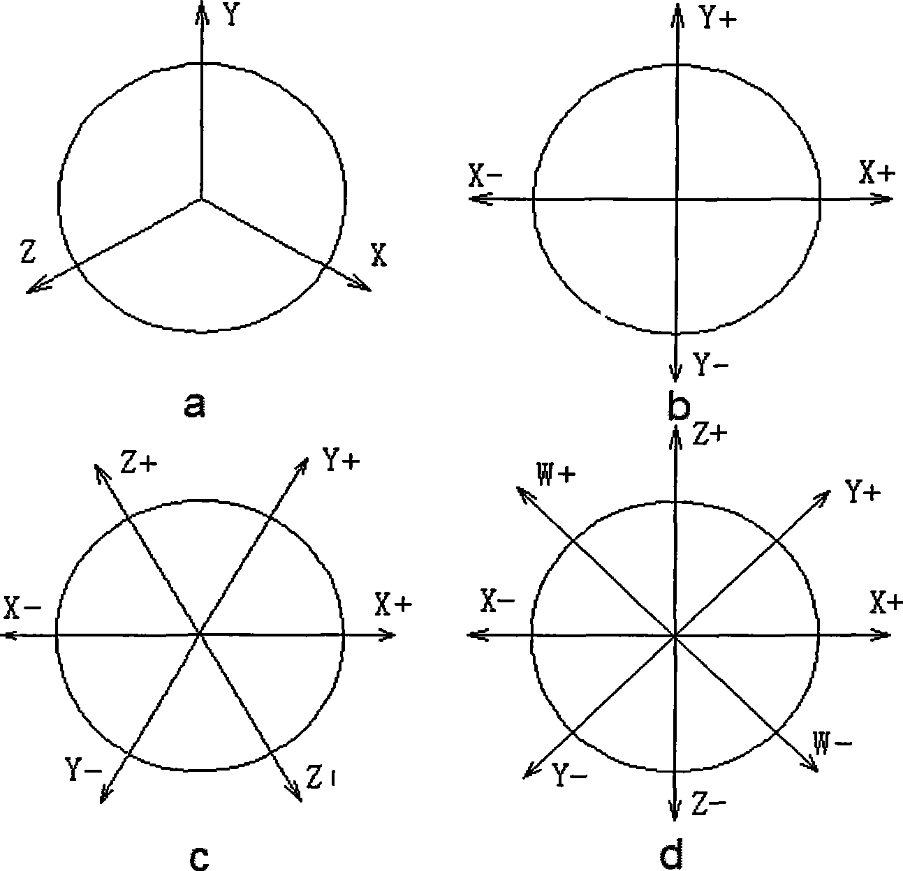
[0028] The design idea of ​​the present invention is as follows: Since any force in a plane can be represented by the resultant force of at least three forces in a certain direction in the plane, figure 1 Shown are the schematic diagrams of several special direction-determining force systems, such as figure 1 The three directions of a determine the force system (X, Y, Z), figure 1 The four directions of b determine the force system (X+, Y+, X-, Y-), figure 1 The six directions of c determine the force system (X+, Y+, Z+, X-, Y-, Z-), figure 1 The eight directions of d determine the force system (X+, Y+, Z+, W+, X-, Y-, Z-, W-), and even more directions determine the force system. Therefore, the inventor proposes to offset the unbalanced force generated by the rotation of the high-speed spindle by controlling the magnitude and direction of the resultant force...


PUM


Abstract

The invention discloses a high speed main shaft electromagnetic type on-line dynamic balance method. The method comprises the following steps: adopting independent static magnetic fields which are produced in parallel in axial direction; and installing sleeves with a lug boss at the shaft segment part of each corresponding magnetic field so as to ensure each static magnetic field to generate an electromagnetic force caused by non-uniform air gaps and the magnitude change of the electromagnetic force is affected by the magnetic field strength and the direction thereof is the same as the direction of the lug boss, thereby overcoming the problem that the direction change of the electromagnetic force can not be accord with the rotating speed because of the over-high rotating speed in traditional electromagnetic balance method. By adjusting the current magnitude of each coil winding in the balance device, balance force with any magnitude (in the predesigned range) and any direction can be achieved. The balance method has the advantages of simple balance device structure, convenient processing and installation, wide dynamic balance speed range and short response time, and can realize timely and effective high speed main shaft on line dynamic balance compensate effect.

Description

Technical field [0001] The invention relates to a high-speed spindle dynamic balancing method, in particular to an electromagnetic online dynamic balancing method for a high-speed spindle. Background technique [0002] With the advancement of science and technology, modern machinery is constantly developing in the direction of high speed, high efficiency and high precision. Therefore, it is more and more important to limit and reduce the vibration of various machinery, that is, to carry out dynamic balance. Especially for high-speed processing machine tools, the level of dynamic balance of the spindle will directly affect the accuracy of the workpieces processed. [0003] The centrifugal force generated when the high-speed spindle rotates can be expressed by the following formula: [0004] F=meω 2 [0005] In the formula, m is the mass of the high-speed spindle system, e is the eccentricity between the center of gravity of the high-speed spindle and its rotation center, ω is the...

Claims


Application Information

Patent Timeline
Patent Type & Authority Applications(China)
IPC IPC(8): H02K15/16G01M1/38
Inventor 徐华马石磊戴攀马求山
Owner XI AN JIAOTONG UNIV
Why Eureka
Try Eureka