Temperature control device for hot rolling mill

A technology of temperature control device and rolling mill, applied in the direction of temperature control, metal rolling, metal rolling, etc., can solve the problems of large temperature change of rolling material, high-precision control of limited temperature, large temperature change of rolling material, etc.

Active Publication Date: 2009-03-25
TOSHIBA MITSUBISHI-ELECTRIC IND SYST CORP
View PDF1 Cites 20 Cited by
  • Summary
  • Abstract
  • Description
  • Claims
  • Application Information

AI Technical Summary

Problems solved by technology

Therefore, due to the operation and stop of the entire cooling device, the temperature of the rolled material changes greatly, and the high-precision control of the temperature is limited.
In addition, the large temperature change of the rolled material also has a negative impact on the thickness accuracy
[0007] On the other hand, in the description of Patent Document 2, there is also the following p

Method used


Image

  • Temperature control device for hot rolling mill
  • Temperature control device for hot rolling mill
  • Temperature control device for hot rolling mill

Examples


Embodiment Construction

[0036] In order to illustrate the present invention in detail, it will now be described with reference to the accompanying drawings. The same or corresponding parts in each drawing are marked with the same reference numerals, and the repeated explanations are simplified or even omitted as appropriate.

[0037] Embodiment 1

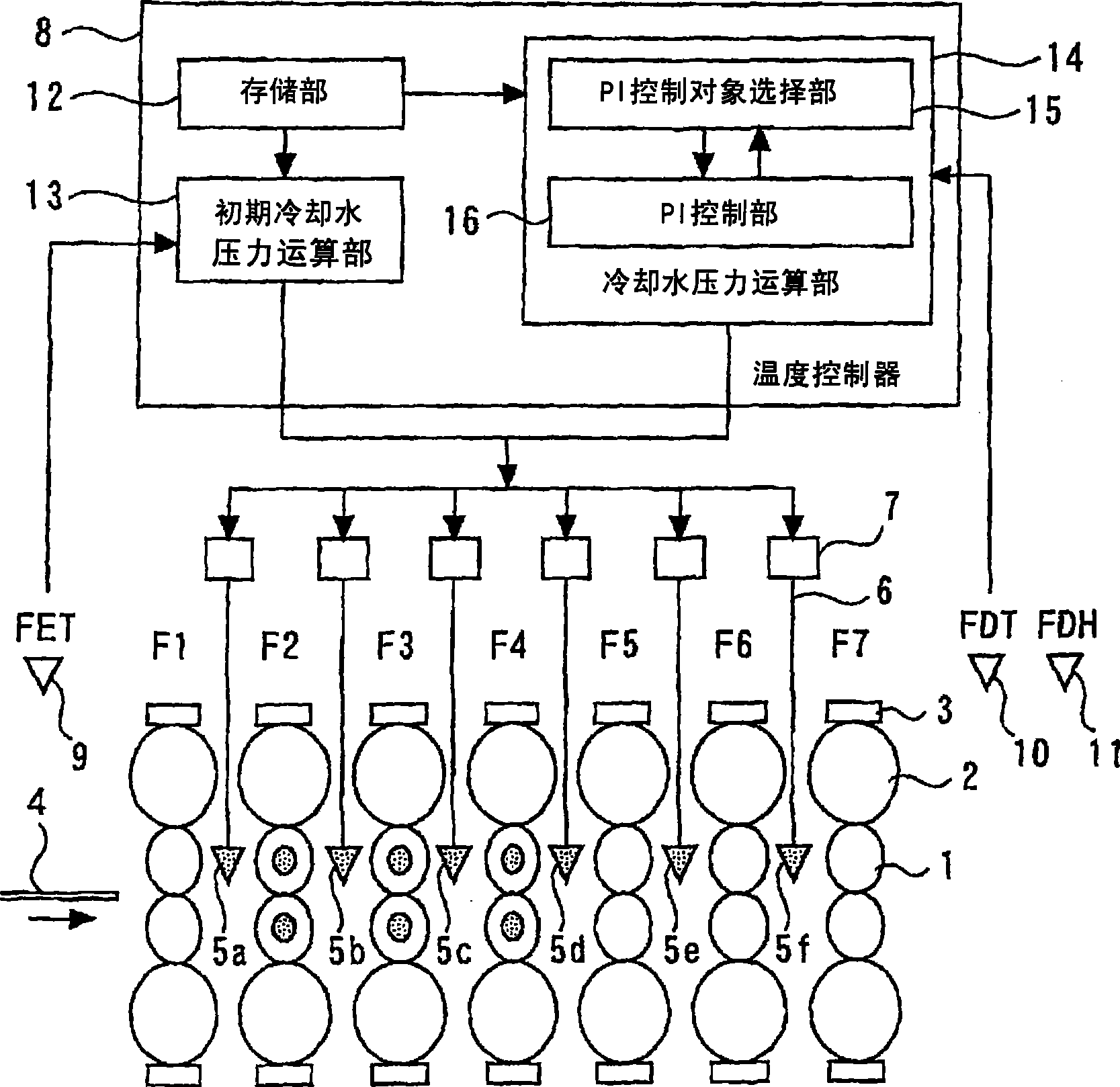
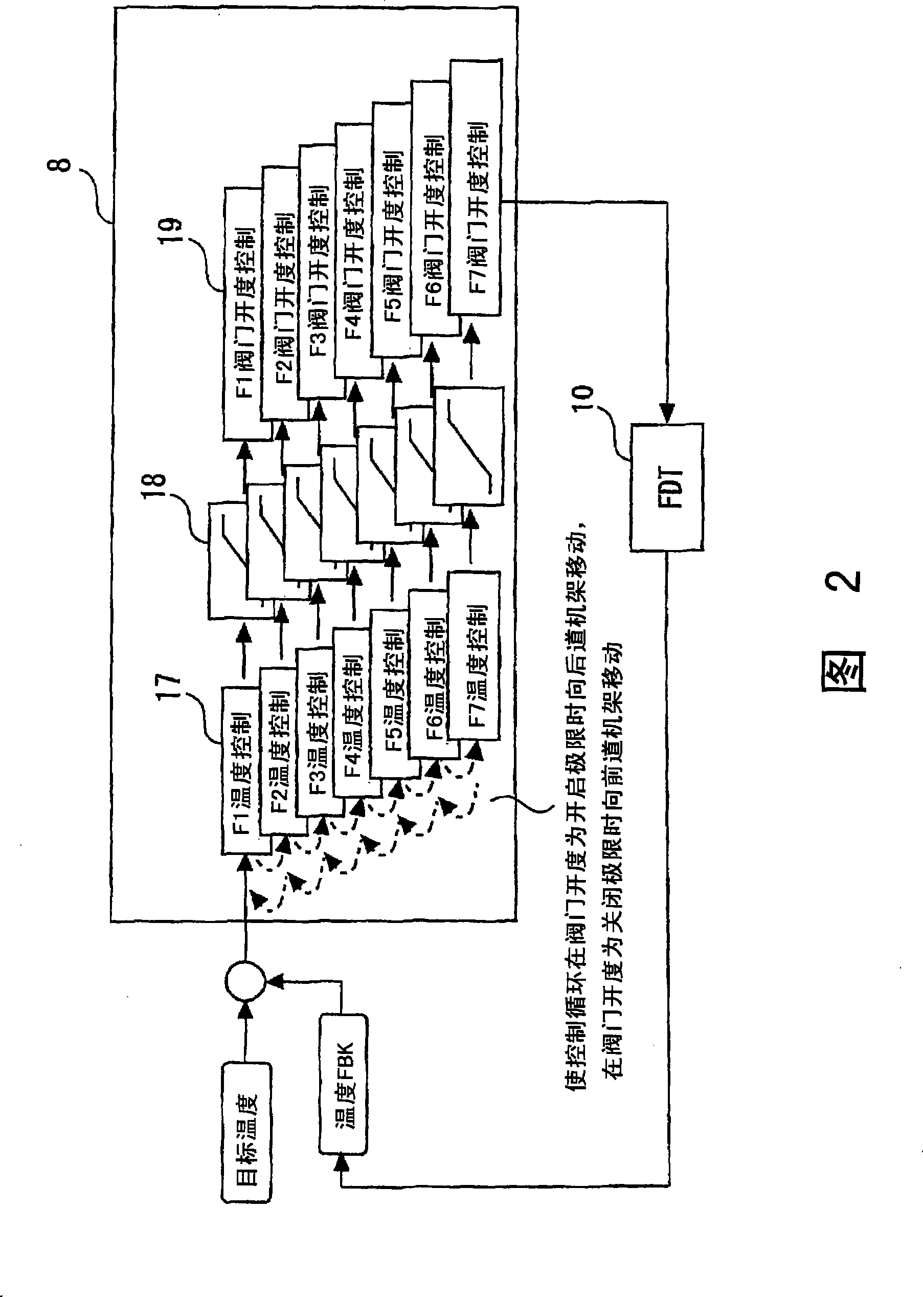
[0038] figure 1 It is an overall configuration diagram showing a temperature control device for a hot rolling mill according to Embodiment 1 of the present invention. Fig. 2 is a block diagram showing a main part of a temperature controller according to Embodiment 1 of the present invention. exist figure 1 And in FIG. 2, as an example, the hot-rolling finishing mill which arrange|positioned 7 rolling stands (F1-F7) in series is shown.

[0039] First, the structure of the temperature control device of the hot rolling mill will be described.

[0040] exist figure 1 And in Fig. 2, there are action roll 1, back-up roll 2, pressing device 3 etc. on each r...


PUM


Abstract

A temperature control unit of hot rolling machine that avoids any sharp temperature change of rolling material at a place near the outlet of the rolling machine to thereby realize a high-precision control of sheet thickness. Accordingly, in a hot rolling machine equipped with multiple rolling stands continually disposed and further with multiple cooling units for cooling of rolling material, first, the cooling water pressure of each of the cooling units is computed using up to the upper limit pressure preferentially from one of the multiple cooling units disposed on the inlet side of the rolling machine on the basis of the target temperature and inlet actual temperature of the rolling material. Subsequently, on the basis of the target temperature and outlet actual temperature of the rolling material, so as to reduce any deviation between the target temperature and the outlet actual temperature, there is computed the cooling water pressure of one of the cooling units in operation disposed nearest the outlet of the rolling machine. At that stage, when the cooling water pressure of the cooling unit under control reaches the upper limit pressure, the control object is changed to the cooling unit disposed adjacent to the outlet of the rolling machine. On the other hand, when the cooling water pressure reaches the lower limit pressure, the control object is changed to the cooling unit disposed adjacent to the inlet of the rolling machine.

Description

technical field [0001] The present invention relates to a temperature control device for a hot rolling mill that sequentially arranges a plurality of rolling mill stands and sequentially rolls heated steel plates, etc., by using these rolling mill stands. Background technique [0002] In a hot rolling mill for rolling a rolled material such as a heated steel plate, it is very important to control the temperature of the rolled material at the exit side of the rolling mill to a target temperature in order to improve the quality of the rolled product. Therefore, various temperature control devices for controlling the temperature of the rolled material at the exit side of the hot rolling mill to a target temperature have been known for a long time. [0003] For example, as a technology of an existing hot-rolling mill temperature control device, it has been proposed to arrange a plurality of cooling devices for cooling rolled materials between a plurality of continuously arranged...

Claims


Application Information

Patent Timeline
IPC IPC(8): B21B37/76B21B45/02
CPCB21B45/0203B21B37/74B21B37/76
Inventor 橘稔
Owner TOSHIBA MITSUBISHI-ELECTRIC IND SYST CORP
Why Eureka
Try Eureka