Main shaft balance device for toolroom machine

A technology of balancing device and machine tool, applied in the direction of manufacturing tools, metal processing machinery parts, metal processing equipment, etc., can solve the difficulty of further improving the lifting speed of the spindle unit, the high manufacturing cost of the lifting driving mechanism, and the load of the lifting driving mechanism. and other problems, to achieve the effects of excellent durability, lightening the load, and improving the lifting speed

Inactive Publication Date: 2009-03-25
PASCAL ENG
View PDF4 Cites 6 Cited by
  • Summary
  • Abstract
  • Description
  • Claims
  • Application Information

AI Technical Summary

Problems solved by technology

[0003] However, this kind of machine tool must support and lift the spindle unit whose weight is larger than the lifting drive mechanism, so the load on the lifting drive mechanism becomes larger.
Therefore, the following problems arise: the positional accuracy of the spindle unit in the vertical direction may decrease, it is difficult to further increase the lifting speed of the spindle unit, and the lifting drive mechanism tends to increase in size, resulting in high manufacturing costs.

Method used


Image

  • Main shaft balance device for toolroom machine
  • Main shaft balance device for toolroom machine
  • Main shaft balance device for toolroom machine

Examples


Embodiment 1

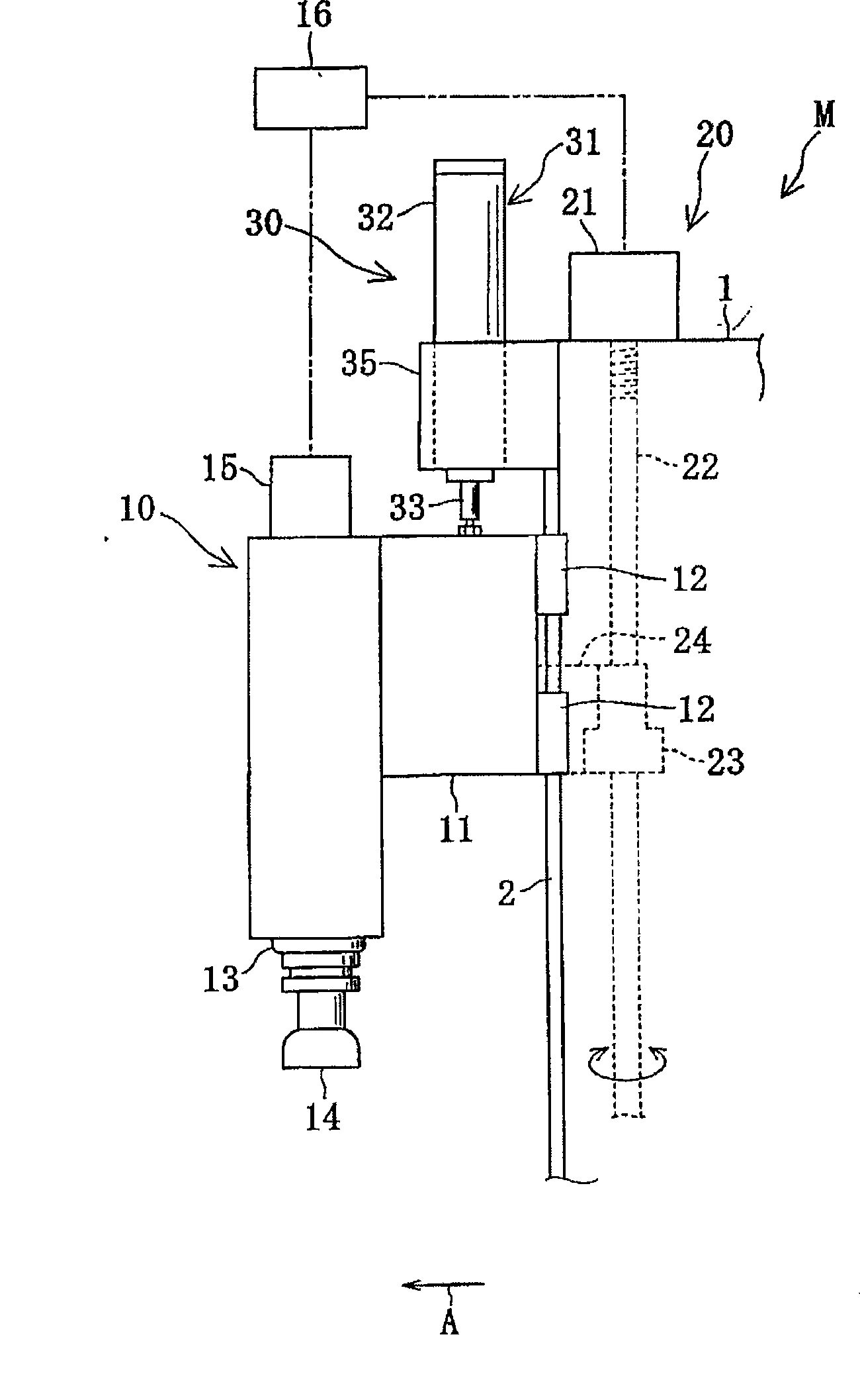
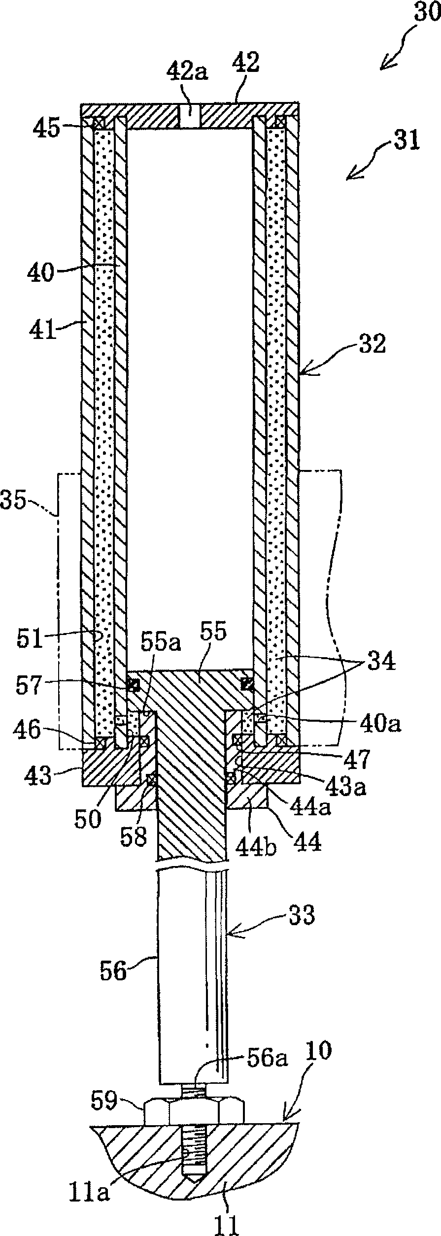
[0037] Such as figure 1 As shown, the spindle balancing device 30 for a machine tool provided by the present invention (hereinafter referred to as the spindle balancing device 30 ) is suitable for a machine tool M such as a vertical machining center. Additionally, the description will figure 1 The direction of the middle arrow A is taken as the front.

[0038] The machine tool M includes: a column body 1, a spindle unit 10 guided in the column body 1 in a liftable manner, and an elevating drive mechanism 20 for lifting and driving the spindle unit 10; The main shaft balancing device 30 (hereinafter referred to as the main shaft balancing device 30 ) has a gas spring 31 that supports the main shaft unit 10 and can reduce the load on the elevating drive mechanism 20 .

[0039] The front end of the cylinder 1 is provided with a vertical guide rail 2, and a slider 12 is fixedly installed on the rear end of the frame member 11 of the main shaft unit 10, and the slider 12 is buckl...

Embodiment 2

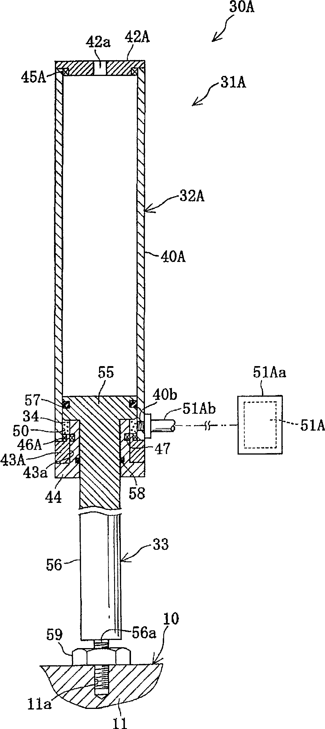
[0062] Such as image 3 As shown, the spindle balancing device 30A includes a gas spring 31A and a compressed gas filling chamber 51A provided independently of the gas spring 31A. The gas spring 31A is used instead of the gas spring 31 of the first embodiment, and is suitable for use in the machine tool M. In addition, the same code|symbol is used for the same part as Example 1, and description is abbreviate|omitted.

[0063] The gas spring 31A includes: a pneumatic cylinder body 32A, a connecting rod 33, and a compressed gas 34. The pneumatic cylinder body 32A, in the pneumatic cylinder body 32 of Embodiment 1, the outer cylinder 41 is omitted, and is formed to be opposite to the inner cylinder 40 and the upper end. Partially modified shapes of the wall member 42 and the lower end wall member 43 form the compressed gas operating chamber 50 inside the pneumatic cylinder body 32A.

[0064] The pneumatic cylinder body 32A includes: a cylinder member 40A, an upper end wall membe...

Embodiment 3

[0067] Such as Figure 4 As shown, the spindle balancing device 30B includes a gas spring 31B, and is adapted to be used in the machine tool M by replacing the gas spring 31 in the first embodiment with the gas spring 31B. The gas spring 31B includes: a pneumatic cylinder body 32B, a connecting rod 33B, and a compressed gas 34. The connecting rod 33B extends upward and downward from the pneumatic cylinder body 32B, and forms a compression chamber containing the compressed gas 34 in substantially the entire interior of the pneumatic cylinder body 32B. Gas actuating chamber 50B.

[0068] The pneumatic cylinder body 32B includes: a cylinder member 60 , an upper end wall member 61 and a lower end wall member 62 fixedly mounted on the upper and lower ends of the cylinder member 60 , and an upper link fixed on the upper end wall member 61 . The guide member 63 and the lower link guide member 64 fixed to the lower end wall member 62 . The cylinder member 60 and the upper and lower ...


PUM


Abstract

A machine tool main spindle balancer that stably pulls and urges a main spindle unit upward to reliably and effectively reduce a load for lifting a means for lifting the main spindle unit, that can be easily applied to existing machine tools, that is excellent in durability and is downsized, and that can be constructed in a simple structure to make the balancer advantageous in production costs. The main spindle balancer (30) has a gas spring (31) having a cylinder body (32), a rod (33), and compressed gas. The gas spring (31) is placed above the main spindle unit (10). The lower end of the rod (33) is connected to the main spindle unit (10) so that the rod (33) can pull and urges the main spindle unit (10) upward by urging force acting on the rod (33) of the gas spring (31). The urging force by the gas spring (31) reduced a load on a lifting mechanism (20).

Description

technical field [0001] The present invention relates to a spindle balancing device for a machine tool, which uses a gas spring to apply a pulling force upward to a spindle unit, thereby reducing the load of a lifting drive device for lifting and driving the spindle unit. Background technique [0002] In the prior art, on a machine tool such as a machining center, a spindle unit is provided, which includes: a spindle for fixing a tool, and an electric motor for rotationally driving the spindle. The spindle unit is supported by a lift drive mechanism and driven up and down. This type of lifting drive mechanism is constituted as follows: generally, it includes a vertical ball screw shaft, a ball screw nut screwed on the ball screw shaft and connected to the main shaft unit, and an electric motor, and the electric motor is used to rotate and drive the balls. The screw shaft, thus, together with the ball screw nut lifts and drives the spindle unit. [0003] However, since this t...

Claims


Application Information

Patent Timeline
Patent Type & Authority Applications(China)
IPC IPC(8): B23Q1/72B23B47/26
CPCB23Q11/0025Y10T409/309352Y10T409/309688
Inventor 北浦一郎木村清二
Owner PASCAL ENG
Why Eureka
Try Eureka