
Mechanical-hydraulic guiding virtual displacement variable hydraulic transformer and variable method

A technology of hydraulic transformer and virtual displacement, applied in the direction of physical quantity changer, fluid pressure converter, mechanical equipment, etc., can solve the problems of low overall efficiency, low efficiency of hydraulic motor and hydraulic pump, slow response speed, etc.

Inactive Publication Date: 2010-08-18
杭州慧翔机电控制工程有限公司 +1
View PDF0 Cites 0 Cited by
  • Summary
  • Abstract
  • Description
  • Claims
  • Application Information

AI Technical Summary

Problems solved by technology

[0004] 1. The efficiency of the hydraulic motor and hydraulic pump itself is not high, and the variable range with relatively high efficiency is very narrow. After being connected in series to form a hydraulic transformer, the overall efficiency is lower and the variable range is narrower
[0005] 2. The hydraulic pressure generated by each plunger in the hydraulic motor and hydraulic pump, while driving the hydraulic motor to rotate, the force acting on the swash plate will also generate a torque consistent with the control direction of the swash plate inclination angle, and the torque As the rotation angle of the hydraulic motor changes, there are as many plungers as possible, but they still cannot completely cancel each other out internally. This part of the fluctuating torque is finally added to the variable mechanism that controls the tilt angle of the swash plate
Therefore, in order to switch to the pump working condition to recover the energy in the process of deceleration and braking, the displacement adjustment mechanisms of the hydraulic motor and the hydraulic pump must cross the zero point, and at the same time, the oil inlet and outlet of the subsequent actuators are also reversed. Not only the stroke of the variable mechanism is large and the response speed is slow, but also it is easy to cause instability near the zero point

Method used


Image

  • Mechanical-hydraulic guiding virtual displacement variable hydraulic transformer and variable method
  • Mechanical-hydraulic guiding virtual displacement variable hydraulic transformer and variable method
  • Mechanical-hydraulic guiding virtual displacement variable hydraulic transformer and variable method

Examples


Embodiment Construction

[0064] In conjunction with the accompanying drawings, the present invention will be described in detail below through specific embodiments.

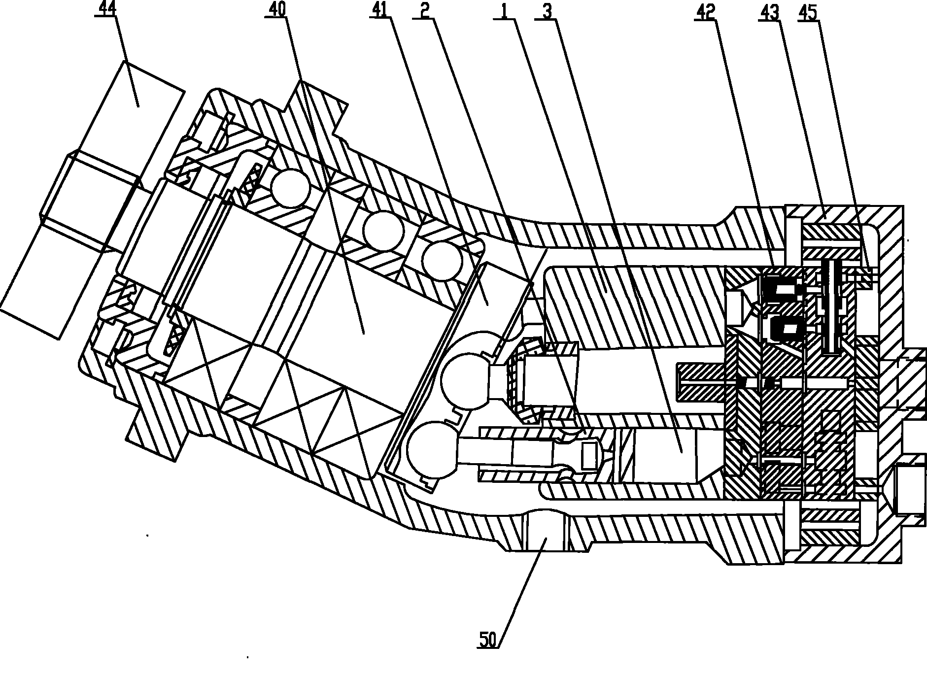
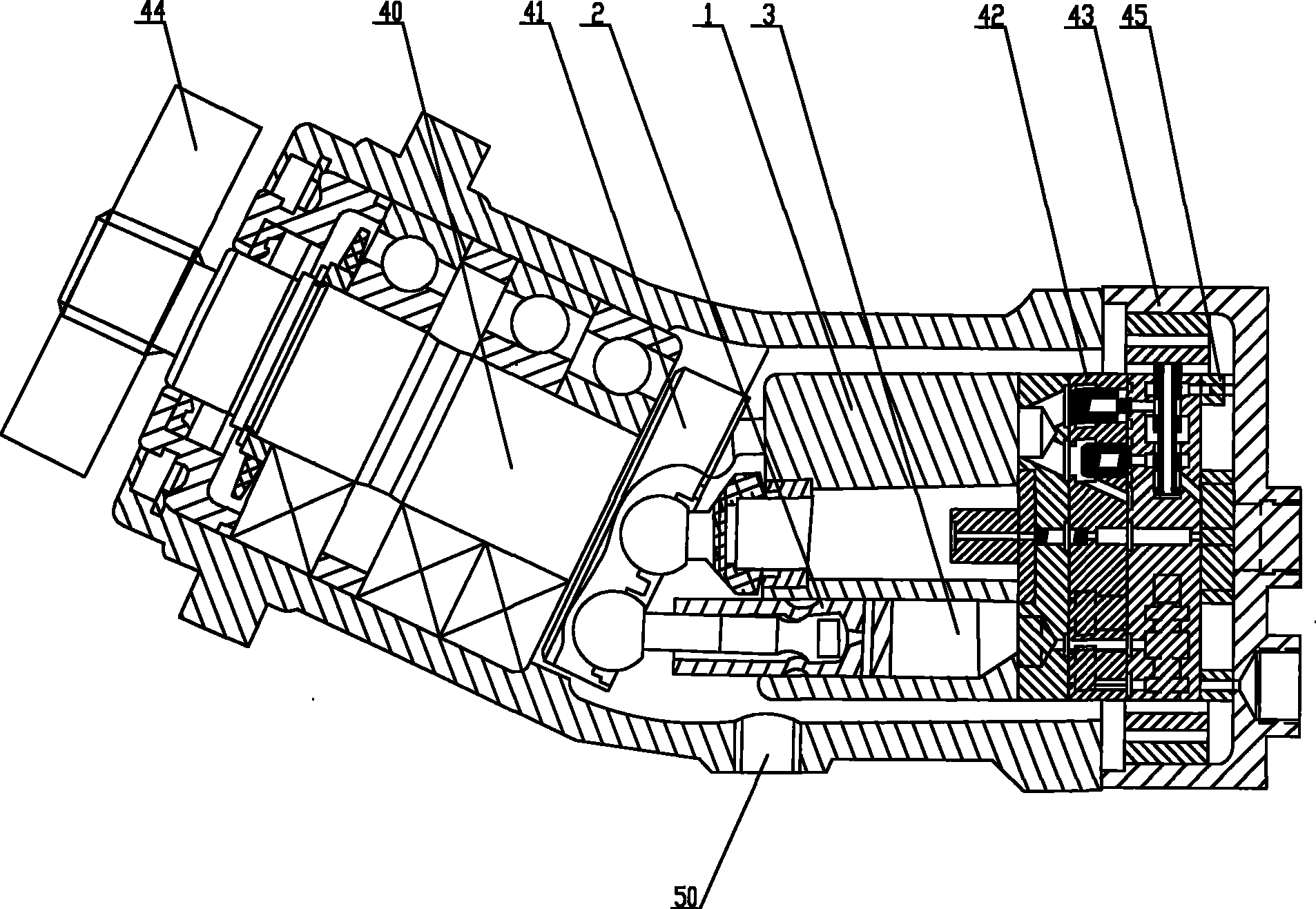
[0065] In this specific embodiment, a machine-hydraulic pilot virtual displacement variable hydraulic transformer is refitted from an ordinary rotary cylinder-type quantitative plunger hydraulic motor.

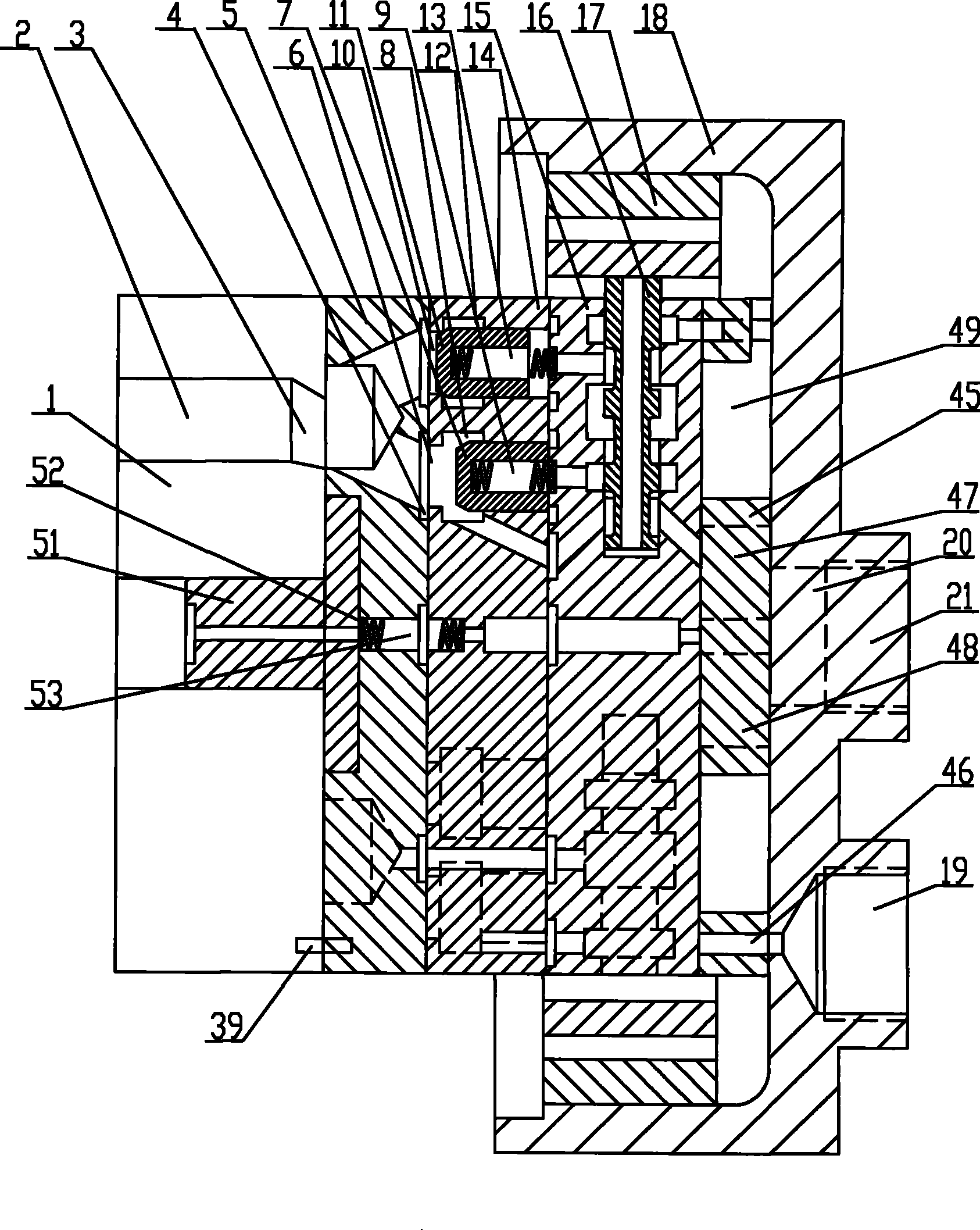
[0066] Install a flywheel with a large moment of inertia on the output shaft of the plunger type quantitative hydraulic motor as a torque filter mechanism; remove the back cover and oil distribution plate of the hydraulic motor at the same time, process the end face of the plunger cylinder into a plane, and A pin hole is processed between every two plunger cavities of the plunger cylinder, and the position of the pin hole is consistent with that of the oil distribution valve body in the present invention. The oil distribution assembly of the present invention is installed on the original rear cover and oil distribution plate position of ...


PUM


Abstract

The invention relates to a hydraulic transformer and a control method thereof which aims at providing a mechanism-liquid lead virtual displacement variable hydraulic transformer and a variable technique. The hydraulic transformer comprises a torque filtering device, a ration swash plate, a plunger case, a plunger and a plunger cavity as well as an oil distribution valve bank, an oil distribution plate and a mechanism-liquid virtual displacement variable driving device. Compared with the prior art, the hydraulic transformer has the beneficial effects such as simplifying the structure, several-fold increasing the high efficient variable control range, saving energy, continuously variable of the pressurization and depressurization operating mode, increasing an order of magnitude in response speed, avoiding the zero crossing problem, and the like.

Description

technical field [0001] The present invention relates to a hydraulic transformer and a control method thereof, and more specifically, the present invention relates to a hydraulic transformer with a virtual displacement variable hydraulic transformer of a machine-hydraulic pilot and a variable variable method. Background technique [0002] The traditional structure of a hydraulic transformer consists of a plunger variable hydraulic motor with a plunger variable hydraulic pump. First, the plunger type variable hydraulic motor relies on the pressure oil to act on the plunger of the motor, so that the motor output shaft obtains a certain torque, and then the plunger type variable hydraulic pump applies the torque to the pump plunger again. Converted to pressure oil again. The change of the variable ratio can be realized by the variable of the hydraulic motor and the hydraulic pump. [0003] Whether it is a plunger-type variable hydraulic motor or a plunger-type variable hydraul...

Claims


Application Information

Patent Timeline
Patent Type & Authority Patents(China)
IPC IPC(8): F15B3/00F15B5/00F15B13/02
Inventor 顾临怡
Owner 杭州慧翔机电控制工程有限公司
Learn More