Supercharge Your Innovation With Domain-Expert AI Agents!

Transformer structure

A technology of transformers and conductors, applied in transformers, fixed transformers, transformers/inductor coils/windings/connections, etc., can solve the problems of miniaturization, space saving and increased application

Active Publication Date: 2011-07-20
DELTA ELECTRONICS INC
View PDF0 Cites 0 Cited by
  • Summary
  • Abstract
  • Description
  • Claims
  • Application Information

AI Technical Summary

Problems solved by technology

However, due to the limitations of the structure of the winding base and coil group, the traditional transformer cannot be further miniaturized, save space, increase applications, solve the problem of heat accumulation, and save assembly time and cost. Therefore, how to develop a transformer structure to solve the problem of traditional technology The problems we are facing are actually important issues at present.

Method used


Image

  • Transformer structure
  • Transformer structure
  • Transformer structure

Examples


Embodiment Construction

[0033] Some typical embodiments embodying the features and advantages of the present invention will be described in detail in the description of the following paragraphs. It should be understood that the present invention can have various changes in different aspects without departing from the scope of the present invention, and The descriptions and illustrations therein are intended to be illustrative in nature and not intended to limit the invention.

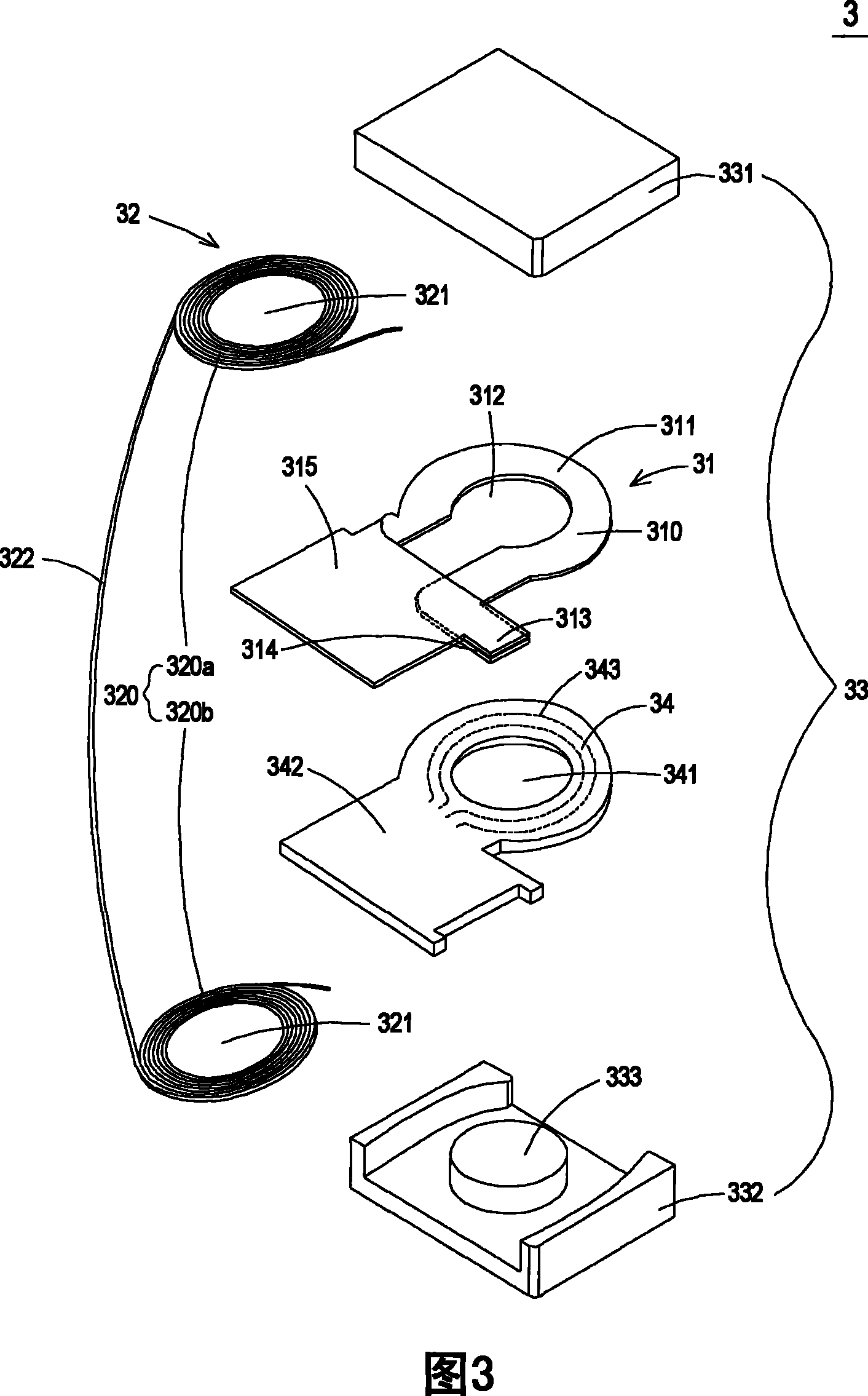
[0034] see image 3 , which is a schematic structural diagram of a transformer according to a preferred embodiment of the present invention. Such as image 3 As shown, the transformer 3 of the present invention includes a first conductor 31, a second conductor 32, an iron core group 33 and a circuit board 34, wherein the first conductor 31 can be used as the secondary winding of the transformer 3, and The second conductor 32 can be used as the primary winding of the transformer 3 , but not limited thereto. The iron core gro...


PUM


Abstract

The invention relates to a transformer which at least comprises: a first conductor, a second conductor, a circuit board and an iron core group. The first conductor is provided with a perforation and at least one electric slice, wherein the electric slice also has an extending part; the second conductor is magnetically coupled with the first conductor and is winded by single conducting line material into a plurality of spiral coil units, wherein, every spiral coil unit is provided with a perforation; the circuit board is provided with a perforation; the iron core group perforates the perforation of the first conductor, the perforation of the circuit board and the perforations of the spiral coil units of the first conductor and coats at least part of the first conductor and the second conductor. The extending part of the first conductor exposes the iron core group, wherein at least one electronic member is arranged on the extending part to assist the fixation of the electronic member and heat dissipation.

Description

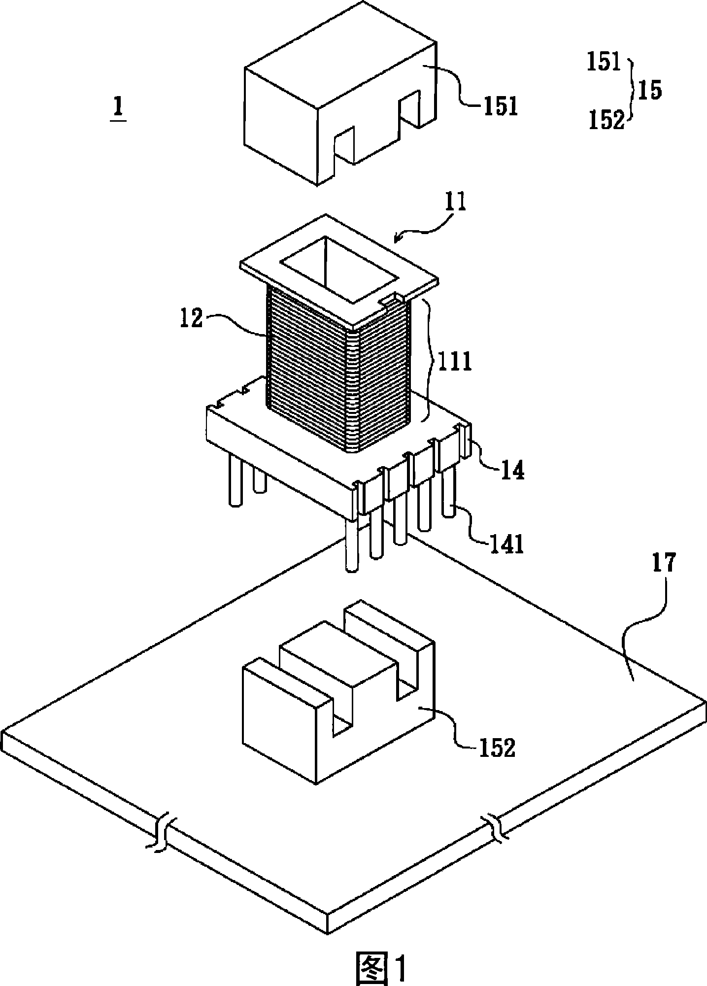
technical field [0001] The invention relates to a transformer structure, especially a transformer structure that can solve the problem of heat accumulation, save space and increase applications. Background technique [0002] Transformers are electronic components that are often used in various electrical equipment to adjust different voltages so that they can reach the applicable range of the power receiving device. see figure 1 , which is a schematic structural diagram of a traditional transformer. Such as figure 1 As shown, the traditional transformer 1 includes a winding base 11 (bobbin), a coil set 12 , a pin base 14 and a core set 15 . The coil set 12 includes a primary winding and a secondary winding, each of which is wound on a winding area 111 of the winding seat 11 by a conductive wire, and the primary winding and the secondary winding are electromagnetically coupled to each other. The pin base 14 is connected to the winding base 11 and includes a plurality of p...

Claims


Application Information

Patent Timeline
Patent Type & Authority Patents(China)
IPC IPC(8): H01F30/06H01F27/30H01F27/28
Inventor 林财申冯文彬陈友钦
Owner DELTA ELECTRONICS INC
Features
  • R&D
  • Intellectual Property
  • Life Sciences
  • Materials
  • Tech Scout
  • Unparalleled Data Quality
  • Higher Quality Content
  • 60% Fewer Hallucinations
Learn More