Control circuit for bistable state permanent magnet operating mechanism

A permanent magnet operating mechanism and control circuit technology, which is applied in circuits, relays, electric switches, etc., can solve problems such as poor breaking capacity, large power loss, and large operating noise, so as to reduce the number, reduce the failure rate, and reduce the opening The effect of the arc

Inactive Publication Date: 2009-04-01
王光顺
View PDF1 Cites 18 Cited by
  • Summary
  • Abstract
  • Description
  • Claims
  • Application Information

AI Technical Summary

Problems solved by technology

However, in actual use, it is found that if pulses are applied to the opening and closing coils during operation, although the purpose of opening and closing can be achieved, the action noise is relatively large and the power loss is also large.
The just-closing speed of this kind of permanent magnet operating mechanism is relatively high, and the closing noise is large, while the just-opening speed is relatively low, and the breaking capacity is poor.

Method used


Image

  • Control circuit for bistable state permanent magnet operating mechanism
  • Control circuit for bistable state permanent magnet operating mechanism

Examples


Embodiment Construction

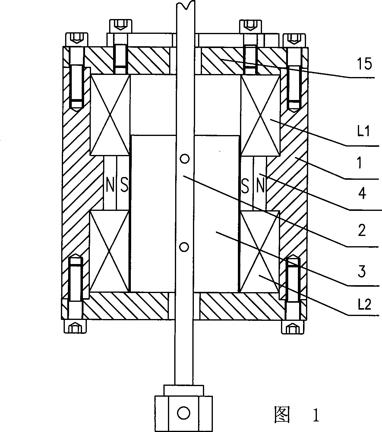
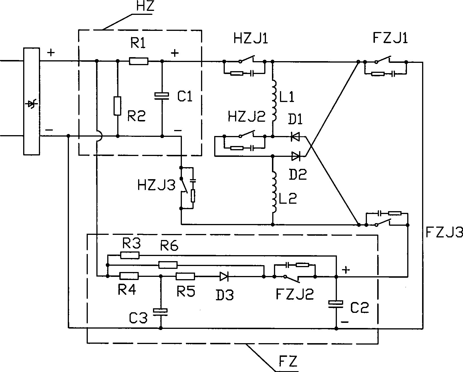
[0012] As shown in the drawings, the control circuit of a bistable permanent magnet operating mechanism according to the present invention includes a permanent magnet operating mechanism and a pulse signal control circuit connected to the pulse coil of the permanent magnet operating mechanism. As shown in Figure 1, the housing 1 of the permanent magnet operating mechanism is provided with an output shaft 2, the output shaft 2 protrudes through the end caps 15 at both ends of the housing 1, the front end is connected with the actuator through a connecting pin, and the rear end is fixedly connected with end cap9. The materials of the shell 1 and the end cover 15 are all ferrous which is easy to conduct magnetism. The contact part between the output shaft 2 and the shell 1 is fitted with an anti-magnetic bushing, and the middle section of the output shaft 2 located inside the shell 1 is fixedly installed with an iron core 3, and the outer side of the iron core 3 is provided with ...


PUM


Abstract

The invention relates to an automatically controlled operational mechanism, in particular to a control circuit of a bistable permanent magnetic operational mechanism, comprising a permanent operational mechanism and an impulse signal control circuit which is connected with an impulse coil of the permanent operational mechanism. The impulse signal control circuit comprises a brake separating energy storing circuit, a brake closing energy storing circuit, a brake separating contact switch and a brake closing contact switch. The impulse coil of the permanent operational mechanism is connected with the circuits by the brake separating contact switch and the brake closing contact switch. And the impulse coil of the permanent operational mechanism and the circuits are used in serial during the brake closing and in parallel during the brake separating. Thus, the high operational speed of gadgets during the earlier stage is lowered, and closing noises are lowered and the service life of the gadgets is prolonged. The instantaneous speed during the initial stage of the closing is improved. The generation of brake separating arc is lowered. The two coils in the bistable permanent operational mechanism are utilized completely. Raw materials are saved, the volume of the mechanism is reduced, and the fault rate is lowered.

Description

technical field [0001] The invention relates to an automatic control operating mechanism, in particular to a control circuit of a bistable permanent magnet operating mechanism. Background technique [0002] The permanent magnet operating mechanism is a mechanical device that uses pulsed electromagnetic force to achieve state transition, and permanent magnetic force to promote the completion of the action and maintain the state. For example, the Chinese patent "A Permanent Magnet Operating Mechanism for a Vacuum Switch", Patent No.: 98220417.5. A kind of such permanent magnet operating mechanism is disclosed, which includes an output shaft, an inherent iron core is placed on the output shaft, a permanent magnet is placed outside the side of the iron core, and a pulse coil is respectively placed outside the two ends of the permanent magnet. The output shaft extends from the center of the two pulse coils. This kind of permanent magnet operating mechanism has the characteristi...

Claims


Application Information

Patent Timeline
Patent Type & Authority Applications(China)
IPC IPC(8): H01H3/28H01H33/38
CPCH01H33/6662H01H47/226
Inventor 王光顺
Owner 王光顺
Why Eureka
Try Eureka