Method, relay and base station for data transmission on relay link

A relay link and data transmission technology, applied in the field of data transmission, can solve the problems of resource waste, size mismatch, and large resource consumption, and achieve the effects of avoiding waste, reducing overhead, and saving air interface resources

Inactive Publication Date: 2009-04-01
DATANG MOBILE COMM EQUIP CO LTD
View PDF0 Cites 19 Cited by
  • Summary
  • Abstract
  • Description
  • Claims
  • Application Information

AI Technical Summary

Problems solved by technology

If the data of each UT is transmitted separately, it will be necessary to use a large number of shared control channels to transmit scheduling signaling, which will cause a great waste of resources
Correspondingly, the receiving end needs to return ACK / NACK information for each user's data separately, which also consumes a lot of resources
[0031] 2. Resource allocation is limited to a certain granularity. Usually resource allocation takes PRB as the basic unit, and the resource size allocated each time needs to be carried out for an integer number of PRBs.
Contradicting with the granularity of resource allocation, the length of the data to be sent changes continuously, which makes the size of the data to be transmitted and the resources allocated for it may not match.
When the data cannot exactly fill an integer number of PRBs, it is necessary to fill the vacant part of the PRB, resulting in a waste of resources
In a data transmission process, the smaller the transmitted data packet, the greater the proportion of resources occupied by the corresponding filling bits, and the lower the transmission efficiency

Method used


Image

  • Method, relay and base station for data transmission on relay link
  • Method, relay and base station for data transmission on relay link
  • Method, relay and base station for data transmission on relay link

Examples


Embodiment 1

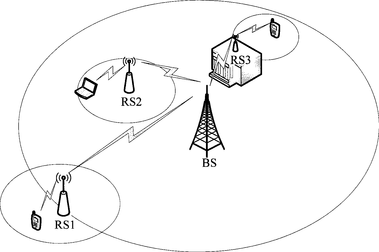
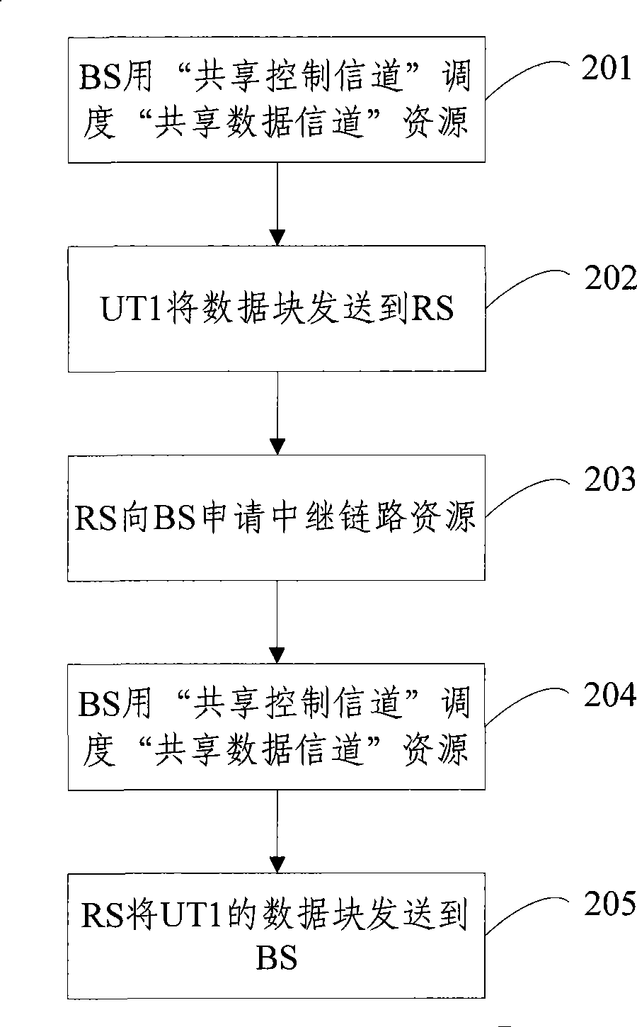
[0111] Embodiment 1: as Figure 4Shown is the flow chart of the uplink data transmission method in the 2-hop relay scenario of the present invention. The system includes terminals UT1, UT2, UT3, etc., a base station BS and a relay RS1. Of course, there are many UTs, BSs, and RSs in the system. In this embodiment, the concept of the present invention is described in a relatively simple case, and the processing of other cases is changed accordingly based on this case, which is similar to this embodiment. The steps are as follows:

[0112] Step 401: For the data blocks of multiple terminals such as UT1, UT2, UT3, etc., the BS uses the "shared control channel" to schedule "shared data channel" resources for them respectively, and the resources are access link resources.

[0113] Step 402: UT1, UT2, UT3, etc. use the resources allocated to them by the BS in step 401 to send data blocks to RS1 respectively.

[0114] Step 403: After receiving the data blocks of UT1, UT2, UT3, etc.,...

Embodiment 2

[0127] The uplink data transmission process of the 2-hop relay scenario described in Embodiment 1 above, when it is a k (k>2) hop relay scenario, as follows Figure 5 As shown, assuming that relays RS A and RS B are deployed in the system, when transmitting uplink data from RS A to RS B, the steps are:

[0128] Step 501: RS A separates the received concatenated data blocks to obtain data blocks respectively belonging to different UTs;

[0129] Step 502: For all data blocks to be sent, RS A determines the sending time of the data block and the next hop destination;

[0130] Step 503: RS A collectively applies for relay link resources from BS for the data blocks to be sent at the same time;

[0131] Step 504: The BS uses the "shared control channel" to schedule "shared data channel" resources, and the resources are relay link resources;

[0132] Step 505: According to the size of allocated resources, concatenate the data blocks that need to be sent at the same time and have th...

Embodiment 3

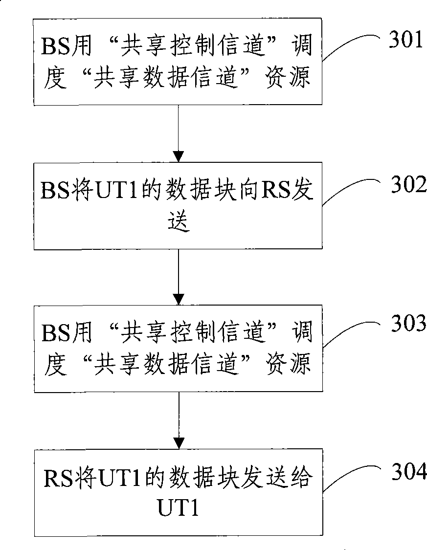
[0155] Such as Figure 7 Shown is a flow chart of a downlink data transmission method in a 2-hop relay scenario. The system includes terminals UT1, UT2, UT3, etc., a base station BS, and a relay RS1. Of course, in the system, there are many UTs, BSs, and RSs. In this embodiment, the idea of ​​the present invention is described in a relatively simple situation. The processing of other situations is based on this situation. resemblance. The steps are as follows:

[0156]Step 701: Before the BS sends downlink data to the relay RS1, it first determines which UTs need to send the data blocks at the time of sending.

[0157] Before the BS sends data to RS1, the BS first determines that the data blocks belonging to UT1, UT2, and UT3 need to be sent at the time of sending.

[0158] Step 702: The BS uses the "shared control channel" to schedule a "shared data channel" resource, which is a relay link resource.

[0159] Step 703: The BS concatenates the data blocks of UT1, UT2, and U...


PUM


Abstract

The invention discloses a method for performing data transmission on a relay link, namely, sending nodes connect the data block with the same sending time and the same receiving node at the next jumping destination in series, and transmit to the receiving node for one time. Meanwhile, the invention also discloses a base station and a relay for realizing the method. According to the method, the base station and the relay of the invention, resource waste caused by using a plurality of signallings when single transmission on the data of each terminal is adopted in the prior art is overcome, meanwhile, excessive filling on the residual parts of the physical resource blocks is avoided, thereby greatly increasing open efficiency, saving open resource.

Description

technical field [0001] The invention relates to a data transmission method in a mobile communication system, in particular to a data transmission method on a relay link in the mobile communication system. Background technique [0002] In order to satisfy user terminals' requirements for full coverage and high capacity of the system, a large number of relay nodes (RS, Relay Station) may be used in future mobile communication systems. The relevant definitions of RS are given below: [0003] RS: a node capable of forwarding terminal data or control signaling between nodes (including: between a base station (BS, Base Station) and RS, between RS and RS, and between RS and a terminal (UT). [0004] Access Link: A wireless link originating or terminating at a UT. [0005] Relay link: a wireless link between BS and RS or a wireless link between RS and RS. [0006] K-hop relay: The data will be sent k times on the air interface from the source node to the target node, that is, rel...

Claims


Application Information

Patent Timeline
Patent Type & Authority Applications(China)
IPC IPC(8): H04W16/10H04W16/26
Inventor 鲍炜高卓寇会如
Owner DATANG MOBILE COMM EQUIP CO LTD
Why Eureka
Try Eureka