Self-ventilating centrifugal pump

A technology of centrifugal pumps and exhaust pumps, applied in the field of centrifugal pumps, to achieve the effect of simple structure and compact implementation

Inactive Publication Date: 2009-04-01
阿尔法·拉瓦尔科灵联合股份有限公司
View PDF6 Cites 8 Cited by
  • Summary
  • Abstract
  • Description
  • Claims
  • Application Information

AI Technical Summary

Problems solved by technology

This construction leads to disadvantageous problems once the centrifugal pump is completely vented and starts to deliver liquid again, since in this case the entire volumetric flow is delivered by the centrifugal pump

Method used


Image

  • Self-ventilating centrifugal pump
  • Self-ventilating centrifugal pump

Examples


Embodiment Construction

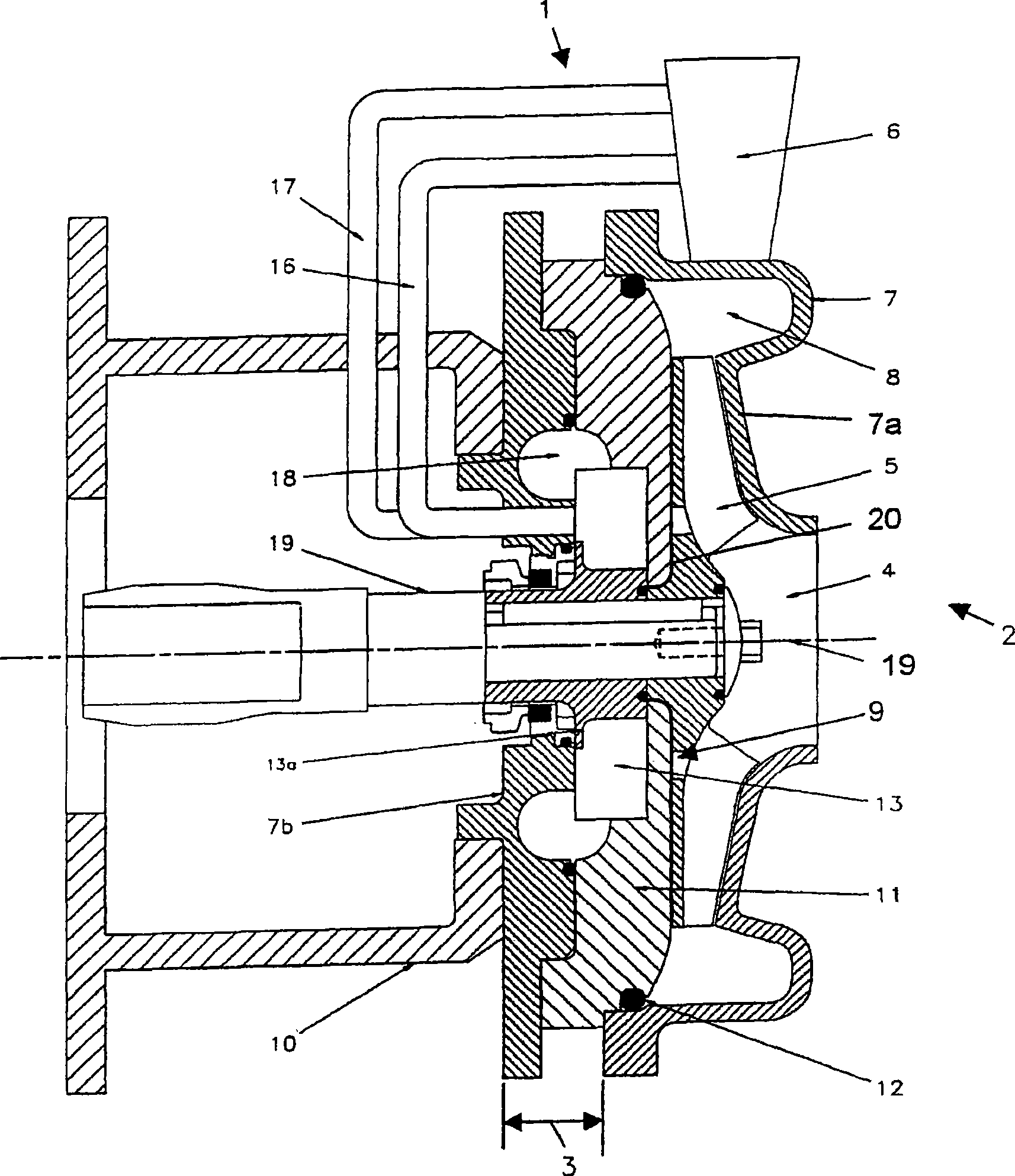
[0027] figure 1 A centrifugal pump 1 according to the invention is shown. The centrifugal pump 1 consists of a centrifugal pump unit 2 and a liquid ring pump 3 . The centrifugal pump device 2 has an inlet region 4 , an impeller 5 and an outlet region 6 . The inlet area 4 , the impeller 5 and the outlet area 6 are connected to one another by a housing 7 .

[0028] The axis of the pump shaft of the centrifugal pump device 2 is at figure 1 Indicated by reference numeral 19.

[0029] An annular channel 8 of the centrifugal pump device 2 is located between the impeller 5 and the outlet area 6 . The centrifugal pump device 2 has a housing 7 composed of a front part 7a and a rear wall 7b. The front part 7a and the rear wall 7b are not the same member. The centrifugal pump 1 is fixed directly to a drive motor (not shown) by means of a bracket 10 fixed on the rear wall 7b.

[0030] The liquid ring pump 3 and its housing 11 are fixed together in a form-fitting manner between the ...


PUM


Abstract

In order to specify a centrifugal pump (1) having a centrifugal pump outlet space (6) and a centrifugal pump suction space (4) and also having an additional ventilation pump (3), which is preferably embodied as a vacuum pump, with a ventilation pump inlet (14) and a ventilation pump outlet (15), which centrifugal pump (1) is of particularly simple construction and which, if required, can be automatically ventilated without complex mechanical switching processes, it is proposed that both the ventilation pump inlet (14) and also the ventilation pump outlet (15) are in each case connected by means of a connecting line (16, 17) to the centrifugal pump outlet space (6) so as to form an auxiliary line.

Description

technical field [0001] The invention relates to a centrifugal pump having a centrifugal pump outlet chamber and an additional exhaust pump, preferably designed as a vacuum pump, which has an exhaust pump intake and an exhaust pump outlet. Background technique [0002] Various embodiments of such pumps have been known for a long time. In addition, every known pump is supposed to solve the problem that a rotary pump or a centrifugal pump does not self-prime in the start-up operating state. [0003] For example, patent document DE1960076A1 discloses a centrifugal pump in which an exhaust pump is provided on the back side. In this known centrifugal pump, both the inlet and the outlet of the centrifugal pump are connected to the inlet of the exhaust pump via valves. For venting, the valves of such known centrifugal pumps are connected in such a way that the inlet of the centrifugal pump is connected directly to the inlet of the venting pump. In contrast, during normal operatio...

Claims


Application Information

Patent Timeline
Patent Type & Authority Applications(China)
IPC IPC(8): F04D9/00F04D9/04
CPCF04D9/042F04D9/006
Inventor 耶斯佩·拉贝格·延森
Owner 阿尔法·拉瓦尔科灵联合股份有限公司
Why Eureka
Try Eureka