Stereophonic sound imaging

A channel, loudspeaker technology used in the field of improving the perceived image and direction of images rendered using a stereo playback system

Inactive Publication Date: 2009-04-01
DOLBY LAB LICENSING CORP
View PDF3 Cites 14 Cited by
  • Summary
  • Abstract
  • Description
  • Claims
  • Application Information

AI Technical Summary

Problems solved by technology

This teaching ignores the fact that, for frequencies above this first band, amplitude distortion caused by comb filtering can be audible

Method used


Image

  • Stereophonic sound imaging
  • Stereophonic sound imaging
  • Stereophonic sound imaging

Examples


Embodiment

[0063] In an aspected exemplary embodiment of the invention, a bank of filters provides a substantially flat magnitude response and a phase response that produces a combined phase shift between channels with alternating bands of 0° and 180°. To avoid undesired fluctuations in the magnitude response, a 90° phase shift can be given to the left channel and a -90° phase shift to the right channel (see Figure 9a , Figure 9b and Figure 9c ). If this is done with a 180° phase shift in one channel, the amplitude will drop towards -∞dB during the phase shift. However, by using only 90° transitions, the maximum dip in frequency is around -3dB. Above about 6kHz, the phase response is less important and can be set to zero for both channels.

[0064] For some filter designs, especially digital filter designs, it may be more efficient not to terminate the phase shift of the band at a defined frequency, but to continue phase shifting the band up to the Nyquist frequency. For other de...


PUM


Abstract

A method for reducing phase differences varying with frequency occurring at certain listening positions with respect to loudspeakers reproducing respective ones of multiple sound channels in a listening space, the phase differences occurring in a sequence of frequency bands in which the phase differences alternate between being predominantly in-phase and predominantly out-of-phase, comprises adjusting the phase in multiple frequency bands in which the multiple sound channels are out-of-phase at such listening positions. Such adjustment of phase includes the frequency bands in which the width of comb filtering pass bands and notches resulting from phase differences at such listening positions would be greater than or commensurate with the critical band width if the phase adjustment were not applied. The listening space may be the interior of a vehicle.

Description

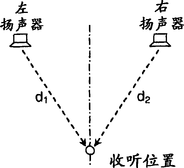
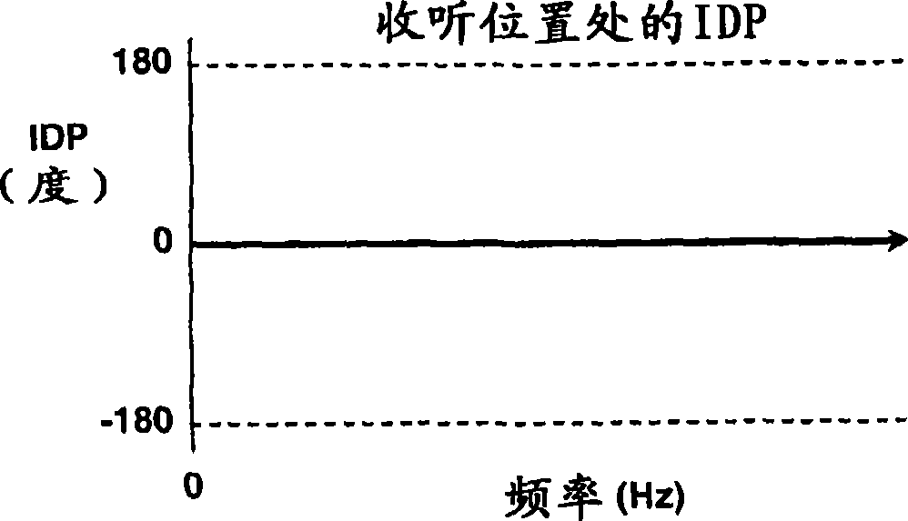
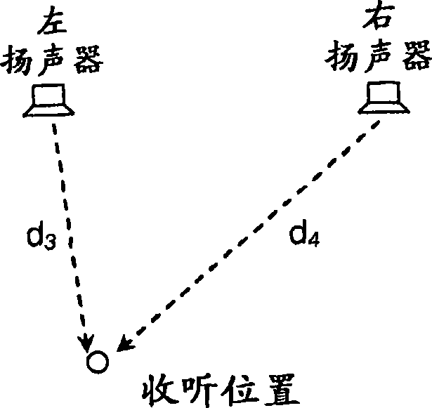
technical field [0001] The present invention relates to audio signal processing. More specifically, the present invention relates to improving the perceived image and image direction presented using a stereophonic playback system, especially where the two listening positions are symmetrical about the central line of such a stereophonic playback system. Aspects of the invention include apparatuses, methods and computer programs stored on computer readable media for causing a computer to perform the methods. Background technique [0002] Two-channel stereo playback systems are nearly ubiquitous in many environments, including live speakers, home music playback, and car stereos. The common effect is that sound through a pair of stereo speakers sounds different at different listening positions relative to the speakers. These variations are primarily caused by differences in the time it takes for sound to travel from each speaker to the listening position and acoustically combi...

Claims


Application Information

Patent Timeline
Patent Type & Authority Applications(China)
IPC IPC(8): H04S1/00
Inventor B·A·库克M·J·史密瑟斯
Owner DOLBY LAB LICENSING CORP
Why Eureka
Try Eureka