LED driving method
A technology of LED drive and main control unit, applied in the field of LED drive, can solve the problems of indecent, unsightly, Christmas tree entanglement, etc., and achieve the effect of saving the number of wires and beautiful appearance
- Summary
- Abstract
- Description
- Claims
- Application Information
AI Technical Summary
Problems solved by technology
Method used
Image
Examples
Embodiment 1
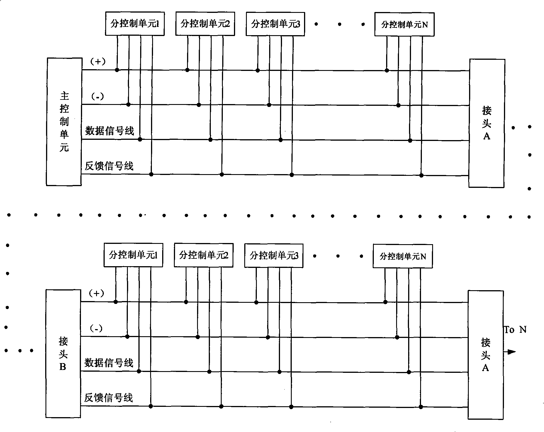
[0018] Embodiment 1: Please refer to the attached figure 1 , in the present embodiment, a main control unit is provided. In the present embodiment, the main control unit selects a single-chip microcomputer system, and the single-chip microcomputer can select a high-speed single-chip microcomputer chip (the high-speed single-chip microcomputer described in this embodiment is not how much the main frequency should reach, and generally adopts the market Single-chip microcomputer chips sold can be used, and the main frequency is crossed, and the effect that can be completed is better), the connection mode of the single-chip microcomputer and peripheral components is selected from the connection mode commonly used by those skilled in the art in the prior art, and the main control unit is connected with one or more sub-control unit, in this embodiment, the sub-control unit also selects the single-chip microcomputer system. All sub-control units are connected, and the data end of eac...
Embodiment 2
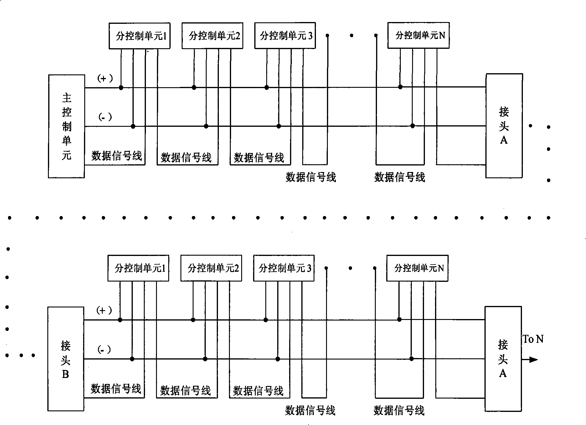
[0021] Embodiment two: Please refer to the attached figure 2 , in this embodiment, there is also a main control unit and a plurality of sub-control units, and only one data signal line is connected between the main control unit and the sub-control units. The sub-control units form a lamp ball chain, and multiple lamp ball chains are connected in series.
[0022] In this embodiment, similar to Embodiment 1, the LED patterns that want to be changed are also set up as a gallery in advance (the gallery includes pictures of patterns composed of different shining LEDs one by one) and then the gallery is converted into a corresponding The data of the LED on or off is stored in the memory of the main control unit. A data package corresponds to a picture, and each picture is compiled according to the actual number of sub-control units needed: assuming 100 sub-control units Taking the control unit as an example, the pre-sent data package of the main control terminal includes: each pic...
Embodiment 3
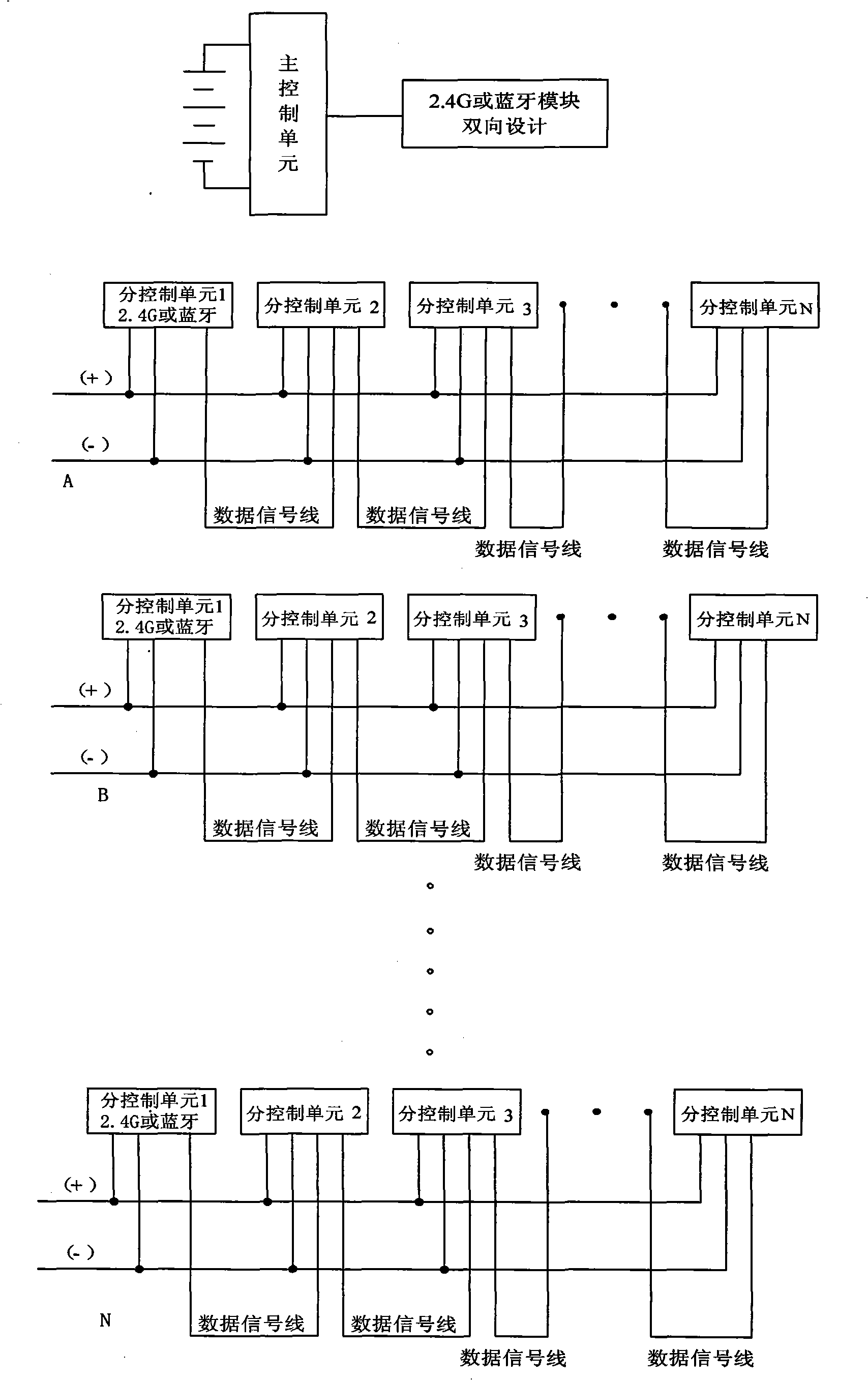
[0024] Embodiment three: Please refer to the attached image 3 , in this embodiment, there is also a main control unit and a plurality of sub-control units, and a plurality of sub-control units form a light ball chain, and the connection mode of each sub-control unit in each light ball chain is the same as that in the second embodiment , the main control unit and a sub-control unit in the light ball chain are correspondingly equipped with a wireless communication module, and the wireless communication module is respectively connected to the data end of the single-chip microcomputer in the main control unit and the sub-control unit equipped with a wireless communication module. In the example, the wireless communication module is used to realize the data transmission between the main control unit and each light ball chain, and the sub-control units in each light ball chain are connected by wire, the connection method is the same as that in the second embodiment, one main control...
PUM
| Property | Measurement | Unit |
|---|---|---|
| Diameter | aaaaa | aaaaa |
Abstract
Description
Claims
Application Information
 - R&D
- Intellectual Property
- Life Sciences
- Materials
- Tech Scout
- Unparalleled Data Quality
- Higher Quality Content
- 60% Fewer Hallucinations
Browse by: Latest US Patents, China's latest patents, Technical Efficacy Thesaurus, Application Domain, Technology Topic, Popular Technical Reports.
© 2025 PatSnap. All rights reserved.Legal|Privacy policy|Modern Slavery Act Transparency Statement|Sitemap|About US| Contact US: help@patsnap.com


