Thermostat apparatus

A thermostat and high-temperature cooling technology, which is applied to valve devices, instruments, valve operation/release devices, etc., can solve the problems of unstable temperature of coolant C and inability to control the opening of main valve 9, etc. Stabilize, increase temperature dominance, and suppress thermal expansion and contraction

Active Publication Date: 2009-04-08
FUJISEIKO
View PDF3 Cites 12 Cited by
  • Summary
  • Abstract
  • Description
  • Claims
  • Application Information

AI Technical Summary

Problems solved by technology

That is, when the temperature of the coolant C rises and a larger opening of the main valve 9 is required, such as Figure 12 Shown in the characteristic of known technology in the present invention, there is the shortcoming that can't control the opening degree of main valve 9
[0018] (3) When the high-temperature coolant channel 3 is closed, because the high-temperature coolant channel 3 is suddenly cut off, temperature hunting occurs immediately after closing, and the temperature of the coolant C is unstable.

Method used


Image

  • Thermostat apparatus
  • Thermostat apparatus
  • Thermostat apparatus

Examples


Embodiment Construction

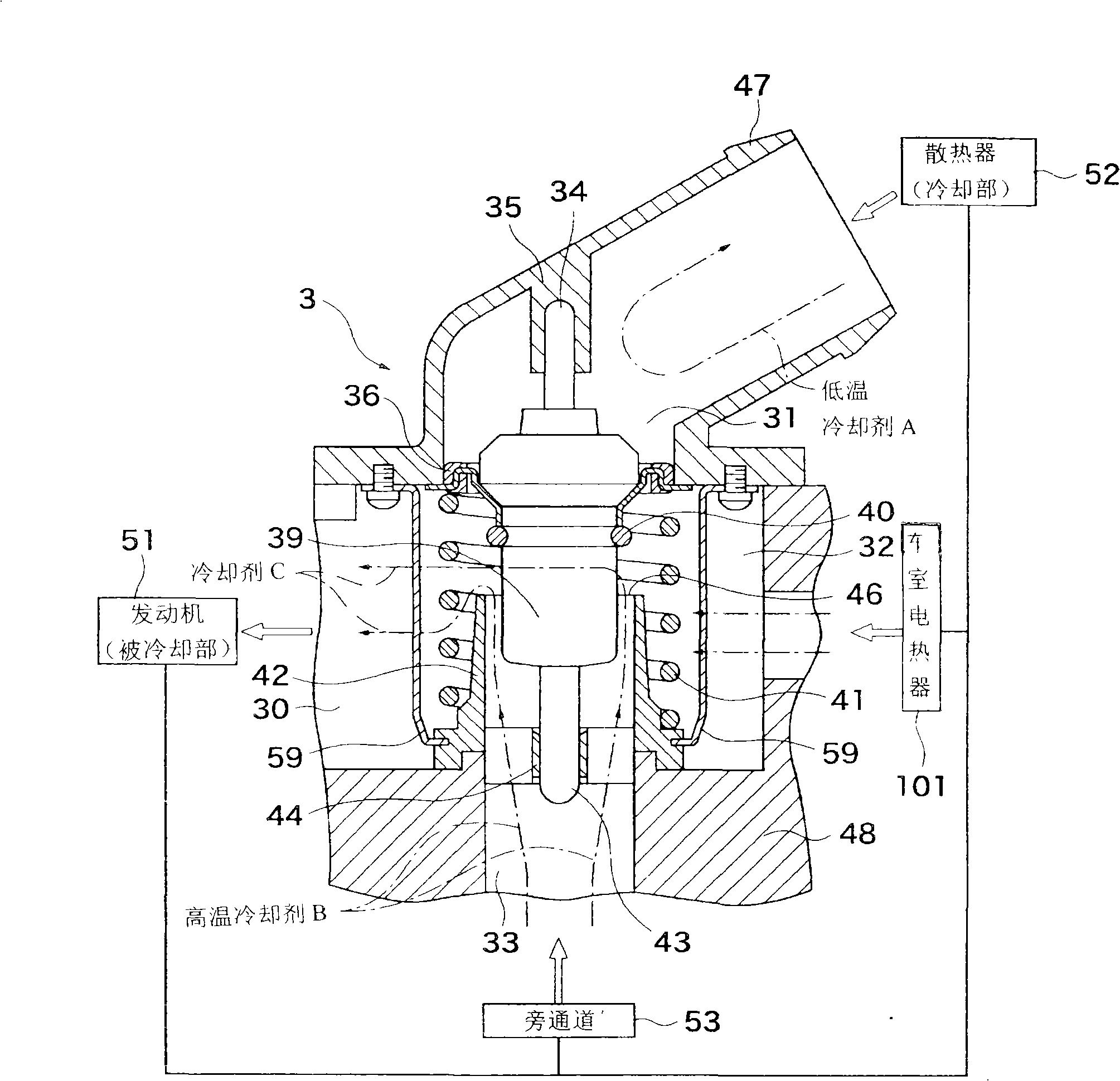
[0088] Hereinafter, as the best embodiment of the present invention, a thermostat device that can be used to control the cooling temperature of an automobile engine will be described in detail with reference to the accompanying drawings.

[0089] Figure 1a The overall structure of the thermostat device 3 of the present invention is shown. In this thermostat device 3, the low-temperature coolant A cooled by the radiator 52 and the high-temperature coolant B supplied from the engine (cooled part) 51 through the bypass passage 53 flow in, and by controlling these mixing ratios, the flow into the engine is controlled. 51 The temperature of the coolant C is within the range of the inlet control mode.

[0090] That is, in this control system, include: high-temperature coolant passage 33, the high-temperature coolant B that flows through engine 51 is directly sent to this high-temperature coolant passage 33 through bypass passage 53; Low-temperature coolant passage 31, flows through ...


PUM


Abstract

A thermostat apparatus comprising a movable temperature sensing member (39) capable of sensing mainly the temperature of high-temperature coolant flowing in from a high-temperature coolant port (33) and driving toward the side of the high-temperature coolant port (33) in dependence upon the sensed temperature; a main valve (36) fitted integrally to the movable temperature sensing member (39) and constructed so as to render a low-temperature coolant port (31) and a mixing compartment (32) openable in conformity to the driving of the movable temperature sensing member (39) toward the side of the high-temperature coolant port (33), thereby controlling the inflow rate of low-temperature coolant from the low-temperature coolant port (31) to the mixing compartment (32); and a high-temperature coolant inducing part (42) communicating with the high-temperature coolant port (33) and adapted to regulate the flow of high-temperature coolant from the high-temperature coolant port (33) toward the surround of the movable temperature sensing member (39) and effect outflow thereof to the mixing compartment (32).

Description

technical field [0001] The present invention relates to a thermostat device mainly for automatic control of coolant for cooling an automobile engine. Background technique [0002] The previous thermostat device 20 was as Figure 10 As shown, there is a housing body 16, which includes: a low-temperature coolant channel 2, which allows the low-temperature coolant A to be cooled by cooling parts such as radiators to flow into the mixing chamber 19, and a high-temperature coolant channel 3, which is located in the above-mentioned low-temperature coolant channel. 2, on the opposite side, the high-temperature coolant B heated by the engine (the part to be cooled) flows into the mixing chamber 19; the coolant delivery channel 4 is the cooling coolant formed by mixing the inflow from the low-temperature coolant channel 2 and the high-temperature coolant channel 3 Agent C is delivered to the engine. The thermostat device 20 also includes: a piston shaft 7, which is supported by the ...

Claims


Application Information

Patent Timeline
Patent Type & Authority Applications(China)
IPC IPC(8): F01P7/16F16K31/68
CPCF01P7/16G05D23/022F01P2037/02G05D23/1333F01P2060/08F16K31/00F16K17/38
Inventor 朴熙完
Owner FUJISEIKO
Why Eureka
Try Eureka