Supercharge Your Innovation With Domain-Expert AI Agents!

Water channel of plastic extrusion machine

A plastic extruder and water tank technology, applied in the field of water tank structure, can solve the problems of unfavorable cleaning, impurity dispersion, high water pressure, etc., and achieve the effects of convenient use and maintenance, easy to be scalded, and easy to clean impurities

Inactive Publication Date: 2009-04-15
SHANGHAI KINGFA SCI & TECH +1
View PDF0 Cites 9 Cited by
  • Summary
  • Abstract
  • Description
  • Claims
  • Application Information

AI Technical Summary

Problems solved by technology

[0004] 1. The water pressure sent into the water inlet is very high, forming a violently rotating water vortex at the water inlet, which is not conducive to the smooth passage of the material strip through the water tank. In serious cases, the water flow will directly spray out from the water inlet to break the material strip;
[0005] 2. During the production of the plastic material strips extruded from the die hole of the extruder head, there are often broken strips under the machine head. It is necessary for the operator to pull the strips in time so as not to affect the production. For the material strip extruded from the hole, the staff must stretch their hands from the edge of the water tank into the middle of the water tank to pull the strip. However, the width of the water tank used in the prior art is only slightly larger than the width of the extruder head, and it is easy to extend the arm obliquely into the water tank. Burned by the material strip extruded from the die hole located on the edge of the machine head, posing a threat to the personal safety of the staff
[0006] 3. Impurities are scattered in the sink, which is not conducive to cleaning;
[0007] 4. When the water outlet is blocked, the water in the tank is likely to overflow due to the continuous water inlet.
[0008] 5. The water outlet is easily blocked by impurities
[0009] After searching, only the technical scheme of changing the material of the cooling water tank from metal to plastic is disclosed, but no technical scheme to improve the above defects has been found.

Method used


Image

  • Water channel of plastic extrusion machine
  • Water channel of plastic extrusion machine
  • Water channel of plastic extrusion machine

Examples


Embodiment 1

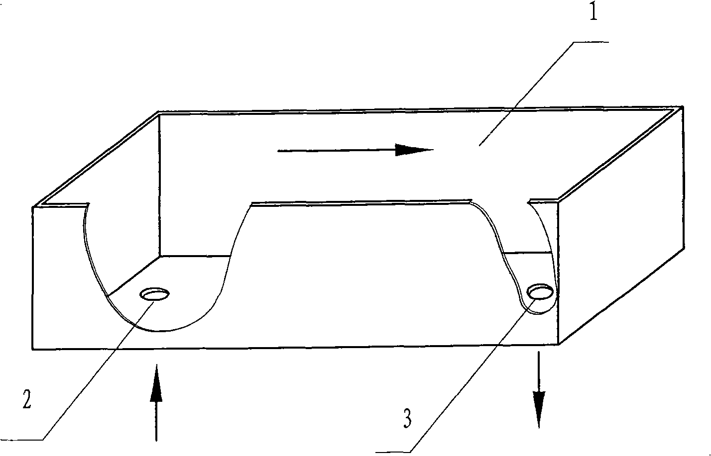
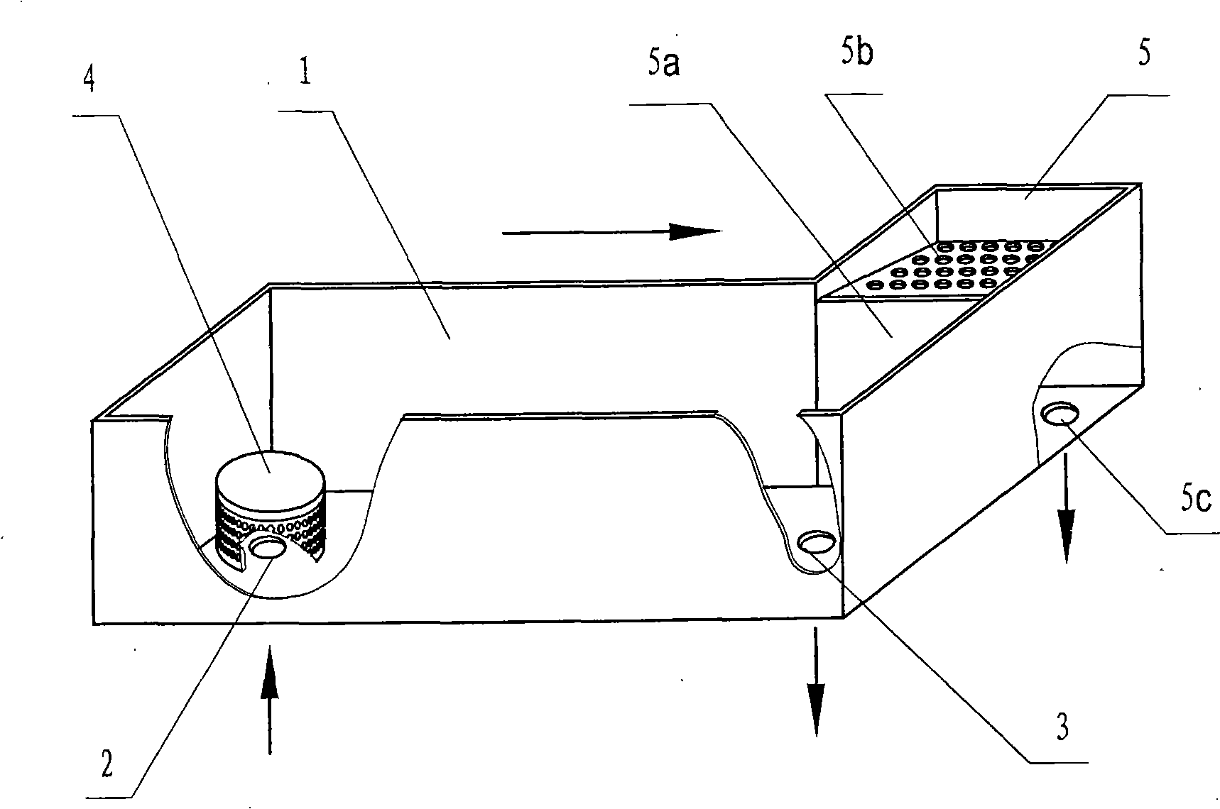
[0041] Such as figure 2 As shown, after the cooling water flows into the tank body 1 from the water inlet 2, the upward water flow will be blocked by the anti-scouring plate in the upper anti-scouring device 4, which effectively reduces the water pressure at the water inlet 2, and then the water flows through the mesh The leakage hole on the plate flows into the tank body 1 gently, and continuously flows towards the water outlet of the tank body. When the water level in the tank is higher than the height of the overflow plate 5a, it will overflow the overflow plate 5a, and pass through the upper inclined collector. The mesh on the miscellaneous plate 5b flows into the below, and flows out of the water tank from the water outlet 5c of the bottom, and the impurities floating with the water will stay on the mesh plate of the miscellaneous plate 5b, which is convenient for centralized removal.

[0042] Such as Figure 5 As shown, in order to prevent the operator from being scald...

Embodiment 2

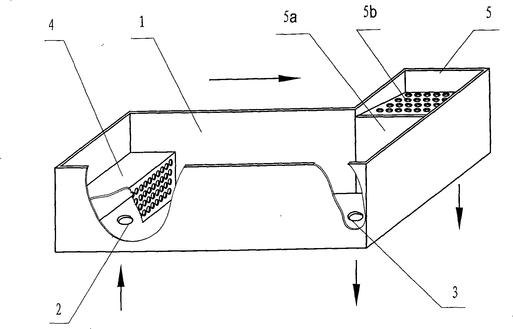
[0045] Such as figure 2 The mesh plate on the periphery of the anti-scouring device 4 and such as Figure 4 The mesh plate with the filter screen cover above the water outlet 3 shown is a wire mesh woven by stainless steel wires, and the rest of the structure is the same as that of Embodiment 1, and will not be repeated here.


PUM

PropertyMeasurementUnit
Apertureaaaaaaaaaa
Sizeaaaaaaaaaa
Widthaaaaaaaaaa

Abstract

The invention relates to a water bath structure for cooling strips extruded by a plastic extruder. A plastic extruder water bath comprises a water bath body and a water inlet and a water outlet arranged at two ends of the bottom of the water bath, and is characterized in that: the part of the water bath body above the water inlet is in a box shape with a downward opening; a bedplate of the water bath body is a flat plate, the side of the water bath body is provided with a mesh plate as an anti-shock device; a side part of a water outlet end of the water bath body is provided with an overflow waste collection groove; a flat overflow plate is arranged between part of the groove and the water bath body; the overflow plate is lower than the groove; a mesh plate is covered above the overflow plate type waste collection plate which is inclined downward along the direction of connection with the overflow plate; and the bottom of the part of the groove is provided with a water outlet. The water bath structure has the advantages of effective relieving water pressure at the water inlet, allowing strips to smoothly pass through the water bath to enter cutting system, well solving the problem of burns caused easily during strip drawing, allowing for easy cleaning of impurities and avoiding water overflowing and blockage to the water outlet.

Description

technical field [0001] The invention relates to an auxiliary device of a plastic extruder, in particular to a water tank structure for cooling strips extruded by the plastic extruder. Background technique [0002] It is known that in the production of modified plastics, since the extruded strips after high-temperature melting from the extruder can only be fed into the pelletizer for pelletizing after cooling down and hardening, the freshly extruded strips must pass through a water tank filled with cooling water. , so as to achieve the effect of cooling and hardening. The water tank used in the production of the prior art is a tank whose overall shape is similar to a cuboid, one end of the water tank is located directly below the extruder head, and the width of the water tank is slightly larger than the width of the extruder head. In order to ensure that the temperature of the cooling water in the water tank is kept within an appropriate range, it is necessary to continuousl...

Claims


Application Information

Patent Timeline
IPC IPC(8): B29C47/88
Inventor 吴晶晶周连风杨定吉甫
Owner SHANGHAI KINGFA SCI & TECH
Features
  • R&D
  • Intellectual Property
  • Life Sciences
  • Materials
  • Tech Scout
  • Unparalleled Data Quality
  • Higher Quality Content
  • 60% Fewer Hallucinations
Learn More