Mechanical seal gear pump

A mechanical seal, gear pump technology, applied in mechanical equipment, rotary piston machinery, pumps, etc., can solve the problem that the pulse damper cannot completely eliminate the pulse, and achieve the effect of light weight, good self-priming performance, and avoidance of pulse

Inactive Publication Date: 2009-04-15
上海黑牛泵业有限公司
View PDF0 Cites 6 Cited by
  • Summary
  • Abstract
  • Description
  • Claims
  • Application Information

AI Technical Summary

Problems solved by technology

[0002] Most of the gear pumps currently on the market use pulses to measure the liquid flow in the pump, and are equipped with pulse dampers to reduce the acceleration of the medium to be measured and reduce the head loss, so that a flow close to laminar flow is generated, but the pulse damper does not Does not completely eliminate pulses

Method used


Image

  • Mechanical seal gear pump

Examples


Embodiment Construction

[0009] The present invention will be further described below in conjunction with accompanying drawing.

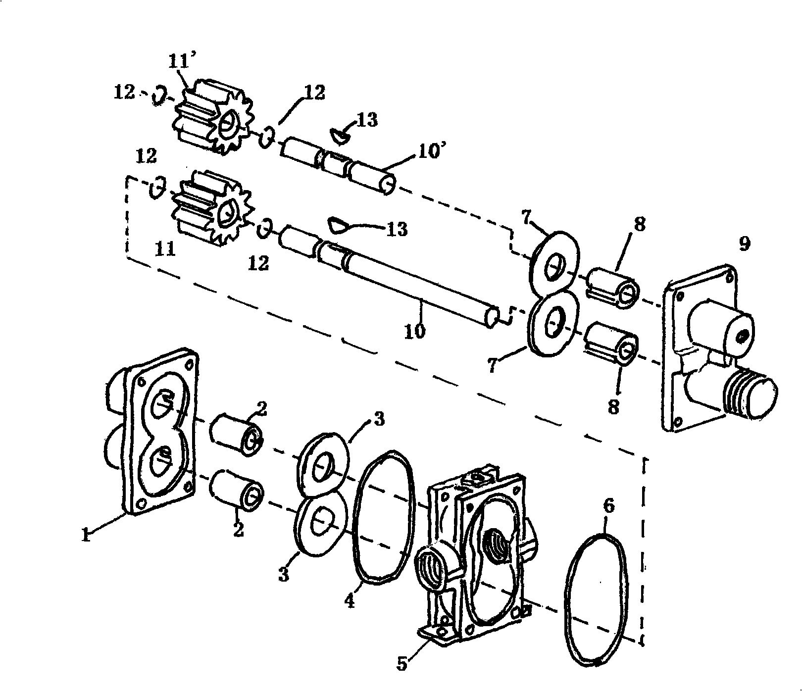
[0010] On the driving shaft 10 and the driven shaft 10' in the middle shell 5, respectively install the driving gear 11 and the driven gear 11' with precise machining and complete meshing degree, and the driving gears are equipped with two snap rings and a key. The shaft 10 and the driven shaft 10' are used to fix the driving gear 11 and the driven gear 11', and the housing O-rings 4, 6 and wear-resistant plates 3, 7 at the front and rear ends of the middle shell 5 are used to ensure sealing and prevent wear. Both the driving shaft 10 and the driven shaft 10' in the cavity of the shell 5 are provided with two annular ring grooves, and a radial key groove is arranged between the two ring grooves, and the ring ring 12 is set in the ring groove. The key 13 is embedded in the keyway to serve the purpose of fixing the gear. When the driving shaft 10 rotates, it drives the bearin...


PUM


Abstract

The invention relates to technical field of a gear pump, in particular to a mechanical sealing gear pump, comprising a rear shell, a middle shell, a front shell, gears, a bearing, an active shaft and a driven shaft. The gear pump is characterized in that shell bodies at the front and the rear sides of the middle shell 5 are respectively provided with an inlet and an outlet; the shaft hole of an active gear 11 is sheathed on the active shaft 10 in the cavity body of the middle shell 5; the shaft hole of a driven gear 11' is sheathed on the driven shaft 10' in the cavity body of the middle shell 5; and the active gear 11 is mutually meshed with the driven gear 11'. Compared with the prior art, the gear pump has the advantages of simple structure, light weight, small volume, good self-absorbing performance, reliable operation and easy maintenance, and uses the fixing gaps of gears for accurately measuring the medium flow, thus avoiding pulse.

Description

[technical field] [0001] The invention relates to the technical field of gear pumps, in particular to a mechanically sealed gear pump. [Background technique] [0002] Most of the gear pumps currently on the market use pulses to measure the liquid flow in the pump, and are equipped with pulse dampers to reduce the acceleration of the medium to be measured and reduce the head loss, so that a flow close to laminar flow is generated, but the pulse damper does not Impulses cannot be completely eliminated. [Content of the invention] [0003] The purpose of the present invention is to overcome the deficiencies of the prior art, and determine the flow rate of the metering pump through the precise gap between the driving gear and the driven gear. [0004] In order to achieve the above purpose, a mechanically sealed gear pump is designed, which includes a rear casing, a middle casing, a front casing, gears, and bearings, and is characterized in that: the front casing 9 is connected...

Claims


Application Information

Patent Timeline
Patent Type & Authority Applications(China)
IPC IPC(8): F04C2/18
Inventor 胡涛胡侃黄姚林周游
Owner 上海黑牛泵业有限公司
Why Eureka
Try Eureka