
Method and device for press mounting water pump impeller

A water pump impeller and press-fitting device technology, which is applied to parts, pumps, and pump components of pumping devices for elastic fluids, and can solve problems such as high production costs, inconvenient production replacement, and impact on efficiency

Active Publication Date: 2009-04-15
FEILONG AUTO COMPONENTS CO LTD
View PDF0 Cites 19 Cited by
  • Summary
  • Abstract
  • Description
  • Claims
  • Application Information

AI Technical Summary

Problems solved by technology

[0002] The press-fitting of the impeller in the water pump assembly is generally the last process. The impeller is relatively small compared to the component. Generally, the component is placed on the workbench, the impeller is placed on the pressure head, and the pressure head touches the impeller to press down. The operation is convenient, but When the impeller is pressed into the pump shaft, it is easy to tilt during placement. The pressing process tilts with the placement direction, which often strains the mating surface of the hole shaft. When the impeller is pressed in place, the hole and the shaft cooperate to form point or line contact, and no surface contact is formed.
Moreover, this structure requires the design of a dedicated pressure head for impellers with the same shape and different diameters, and different bases for different pulley shapes, which result in higher production costs.
The annual production cost is as high as 100,000 yuan, and it is inconvenient to change production, which affects efficiency

Method used


Image

  • Method and device for press mounting water pump impeller

Examples


Embodiment Construction

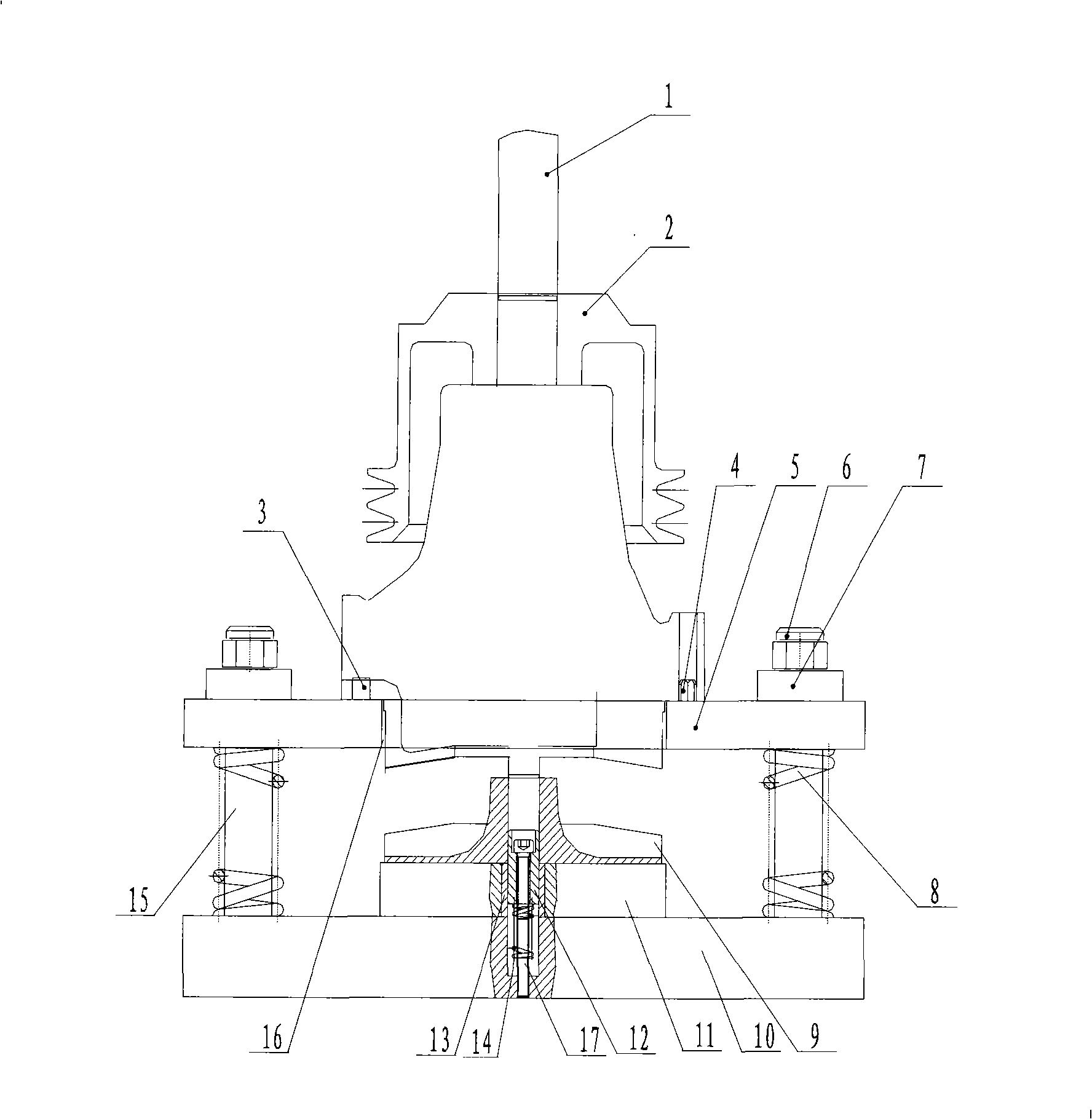
[0012] Such as figure 1 The water pump impeller pressing device shown has a support plate 10, four guide columns 15 are arranged on the four corners of the support plate, each guide column 15 is equipped with a support spring 8 outside, and a positioning plate 5 is set on the guide column 15 , the support spring 8 is located between the support plate 10 and the positioning plate 5 , and the upper end of the guide column 15 presses the positioning plate 5 through the washer 7 and the nut 6 . The center position of the support plate 10 is fixed with a positioning block 11, and the center of the positioning block and the support plate is provided with a step hole. The step hole is located at the position of the positioning iron and is fitted with a bushing 13. Block 11, the water pump impeller 9 can be set on the impeller positioning mandrel 12, a compression spring 14 is provided in the step hole, the compression spring 14 supports the impeller positioning mandrel 12, and the so...


PUM


Abstract

The invention discloses a pump impeller press mounting device in the pump processing technology field, and a press mounting method thereof; the pump impeller press mounting device is provided with a support plate and is characterized in that four guideposts are arranged on the support plate; a support spring is sheathed at the external part of each guidepost; locating plates are sheathed on the guideposts; the support springs are positioned between the support plate and the locating plates; the central position of the support spring is fixed with a locating block; the center of the locating block is provided with a flexible impeller positioning core axle; the central position of the locating plate is provided with a communicating pore and the impeller can pass through the communicating pore; the locating plate is provided with two positioning pins; positioning holes which are matched with the positioning pins are arranged on a pump component; the matching of the positioning pins and the positioning holes, and the matching of the end face of the pump component and the upper face of the locating plate form one-face two-pin positioning and cause the center of the pump component and the flexible impeller positioning core axle mechanism to be concentric. Compared with the prior art, the invention has compact structure, easy operation and high production efficiency, causes the impeller and a rotating shaft to be assembled accurately, and saves the manufacturing cost of a fixture.

Description

technical field [0001] The invention belongs to the technical field of water pump processing, and in particular relates to a water pump impeller press-fitting device and a press-fitting method thereof. Background technique [0002] The press-fitting of the impeller in the water pump assembly is generally the last process. The impeller is relatively small compared to the component. Generally, the component is placed on the workbench, the impeller is placed on the pressure head, and the pressure head touches the impeller to press down. The operation is convenient, but When the impeller is pressed into the pump shaft, it is easy to tilt during placement. The pressing process tilts with the placement direction, which often strains the mating surface of the hole shaft. When the impeller is pressed in place, the hole and the shaft cooperate to form point or line contact, and no surface contact is formed. . And this structure requires the impellers of the same shape and different ...

Claims


Application Information

Patent Timeline
Patent Type & Authority Applications(China)
IPC IPC(8): F04D29/60
Inventor 冯长虹江慧丽赵书峰王瑞金闫合春余春华
Owner FEILONG AUTO COMPONENTS CO LTD
Learn More