Method for enlarging optical fiber gyroscope range

A technology of fiber optic gyroscope and range, which is applied in the direction of Sagnac effect gyroscope, etc., can solve the problems that fiber optic gyroscopes cannot be distinguished, cannot solve the problems of power-on and start-up of fiber optic gyroscopes, and output wrong angular rate signals, etc., and achieve weight and cost increases , increase the range, and expand the effect of the application field

Active Publication Date: 2009-04-15
BEIJING AEROSPACE TIMES OPTICAL ELECTRONICS TECH
View PDF0 Cites 23 Cited by
  • Summary
  • Abstract
  • Description
  • Claims
  • Application Information

AI Technical Summary

Problems solved by technology

Although the cross-stripe method can increase the range of the fiber optic gyroscope, it cannot solve the problem of power-on and start-up of the fiber optic gyroscope

Method used


Image

  • Method for enlarging optical fiber gyroscope range
  • Method for enlarging optical fiber gyroscope range
  • Method for enlarging optical fiber gyroscope range

Examples


Embodiment Construction

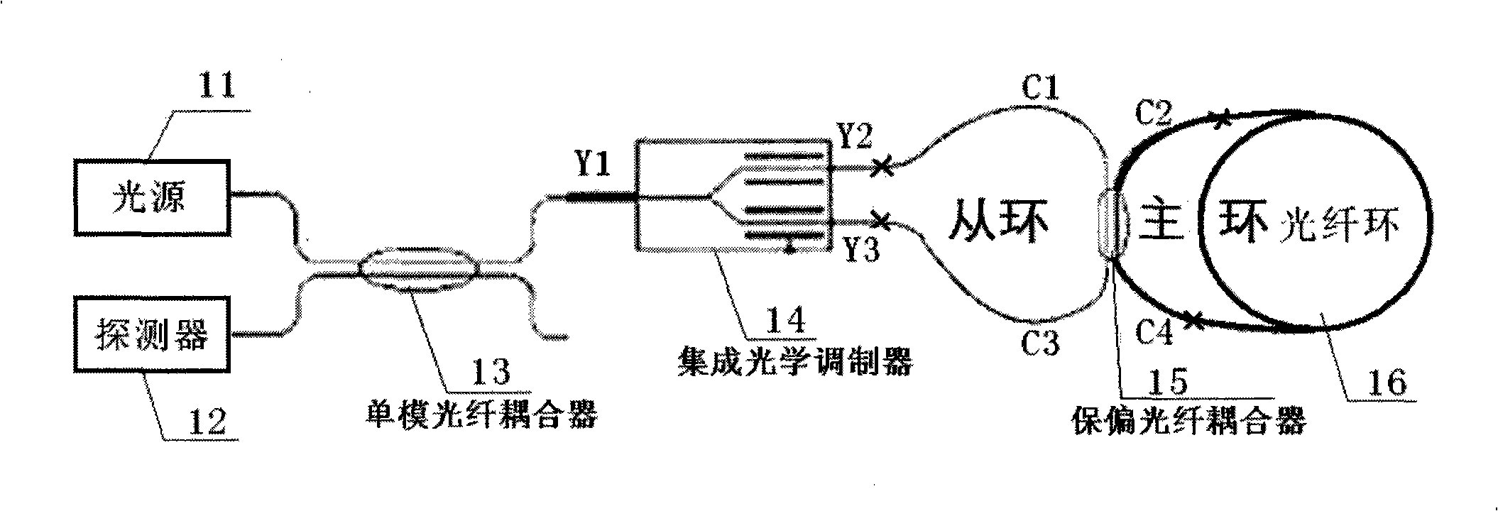
[0038] 1. Fabrication of optical fiber gyroscope double sensitive ring optical path

[0039] Such as figure 1 As shown, the optical fiber gyroscope double sensitive ring optical path includes a light source 11, a detector 12, a single-mode fiber coupler 13, an integrated optical modulator 14, a polarization maintaining fiber coupler 15 and a fiber ring 16, and the polarization maintaining fiber coupler 15 is located in the integrated optical Between the modulator 14 and the fiber ring 16, the C1 and C3 tail fibers of the polarization maintaining fiber coupler 15 are respectively connected to the Y2 and Y3 end pigtails of the integrated optical modulator 14, and the C2 and C4 ends of the polarization maintaining fiber coupler 15 The end pigtails are respectively connected to the two pigtails of the optical fiber ring 16, Y2, C1, C4, optical fiber ring, C2, C3 and Y3 form the Sagnac main sensitive ring, and the Y2, C1, C3 and Y3 pigtails form the Sagnac sensitive ring.

[0040]...


PUM

PropertyMeasurementUnit
Lengthaaaaaaaaaa
Lengthaaaaaaaaaa

Abstract

The invention relates to a method for increasing the measuring range of an optical fibre gyro. The method comprises: the design of a double sensing ring light path, the double demodulation of a double sensing ring, increasing the spanning stripe measuring range, stripe recognition and speed correction. Based on the spanning stripe treatment, Sagnac with larger measuring range is used for judging interferometric fringe level of the work of the optical fibre gyro formed by Sagnac main sensing rings according to the output angular speed of the sensing rings, and the output angular speed of the Sagnac main sensing rings is corrected, thus increasing the measuring range of the optical fibre gyro, solving the problem that the optical fibre gyro can not be started by electricity in the condition of fast spinning and expanding the application field of the optical fibre gyro; especially, the application of the high precision optical fibre gyro has important significance.

Description

technical field [0001] The invention relates to a method for increasing the measuring range of an optical fiber gyroscope, which is especially suitable for an optical fiber gyroscope powered on and started under high-speed rotation. Background technique [0002] With the continuous deepening and expansion of the application of fiber optic gyroscopes, the demand for high-precision and large-range fiber optic gyroscopes is becoming increasingly urgent in some fields, and there is a mutual constraint relationship between the range index and accuracy index of fiber optic gyroscopes, which leads to fiber optic gyroscopes in high-precision, large-range Applications in large ranges are hampered. [0003] In order not to sacrifice the accuracy performance of the fiber optic gyroscope but to increase its range, the cross-stripe method can be used to increase the range of the fiber optic gyroscope. Although the cross-stripe method can increase the measuring range of the fiber optic g...

Claims


Application Information

Patent Timeline
IPC IPC(8): G01C19/72
Inventor 高峰王巍王学锋于海成丁东发李晶付铁钢
Owner BEIJING AEROSPACE TIMES OPTICAL ELECTRONICS TECH
Why Eureka
Try Eureka