Optical fiber grating static water level
A technology of static level and fiber grating, which is applied to instruments, scientific instruments, and the measurement of the change force of optical properties of materials when they are stressed, can solve problems such as poor dynamic performance, low precision, and leakage, and achieve Simple networking, high precision, and the effect of remote real-time reading data
Inactive Publication Date: 2010-12-01
上海森首科技股份有限公司
View PDF0 Cites 1 Cited by
- Summary
- Abstract
- Description
- Claims
- Application Information
AI Technical Summary
Problems solved by technology
The traditional static level adopts traditional measurement methods such as pressure type, capacitive type, and float type, all of which are based on electrical sensors, which have weak anti-interference ability, low precision, short service life, weak networking ability, and poor dynamic performance. There are disadvantages such as winding, blockage, leakage, medium corrosion, and inconvenient maintenance.
Method used
View moreImage
Smart ImageViewing Examples
Examples
Embodiment Construction
Login to View More PUM
 Abstract
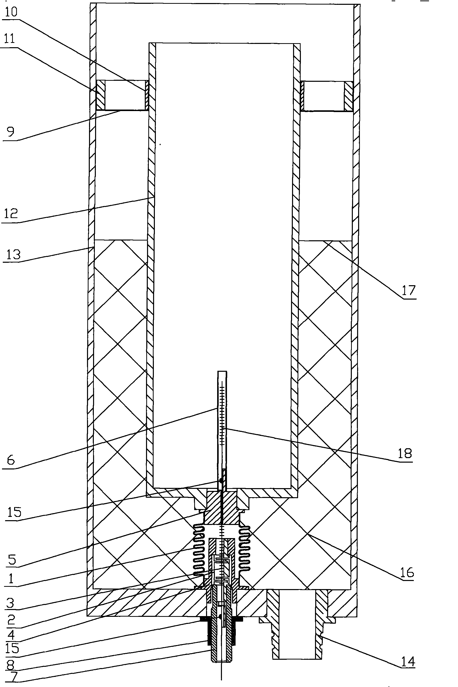
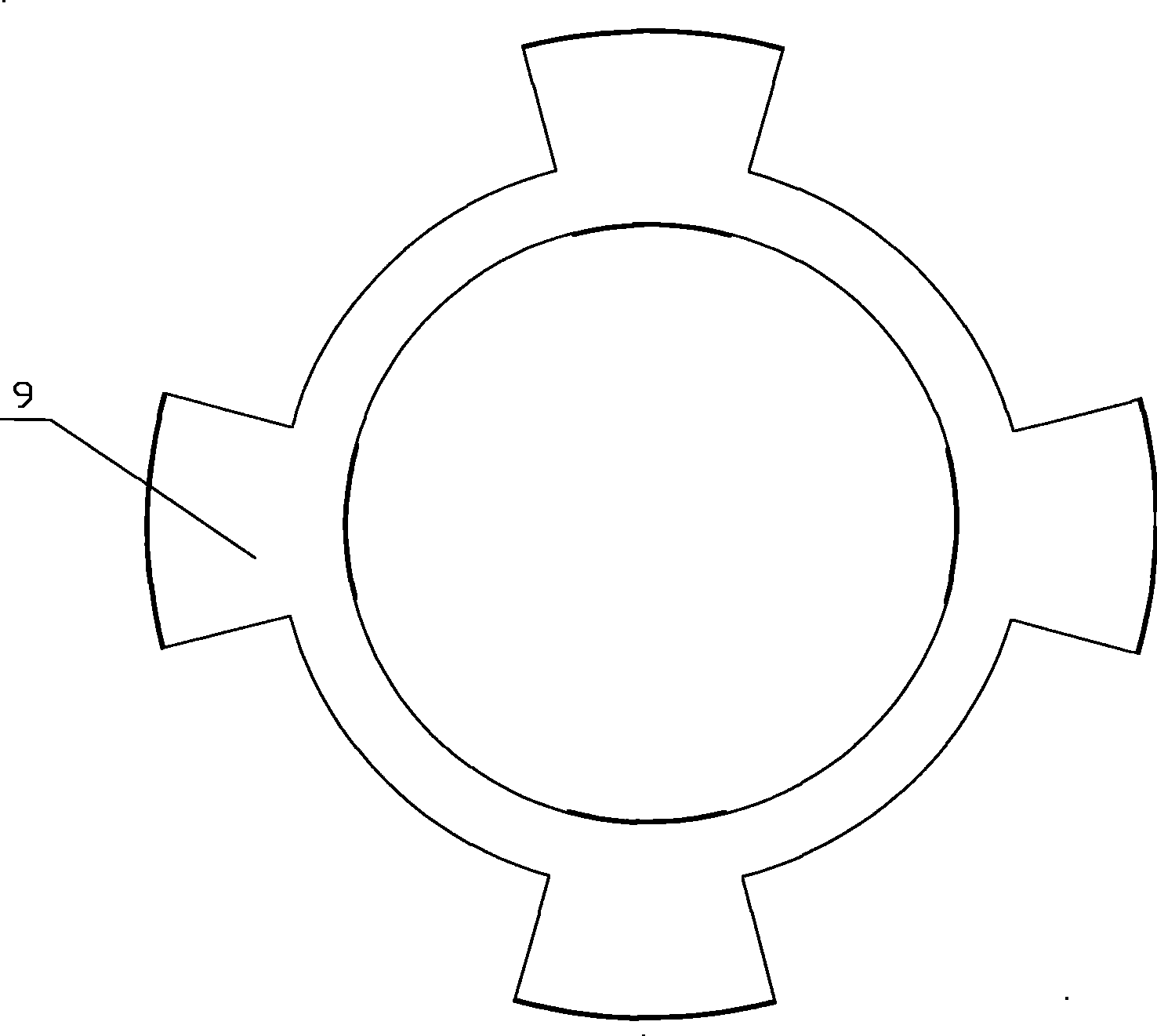
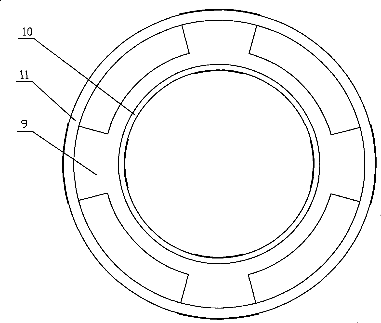
The invention relates to an optical fiber grating static force level which comprises a corrugated tube, an elastic beam, an optical fiber grating, a connector I, a connector II, an optical fiber grating temperature sensor, a screw tube, a limiter, a pontoon and an external cylinder. Compared with the prior art, the optical fiber grating static force level uses the theory that the reflection wavelength of the optical fiber grating varies with the change of the tensile force exerted on the grating, and obtains the change of the tensile force exerted on the fiber grating by monitoring the variance of the wavelength of light reflected by the optical fiber grating so as to calculate the buoyancy force exerted on the pontoon and the liquid level of the pontoon; the level of the liquid in the pontoon can be measured using the optical fiber grating with the characteristics; the structure also comprises an optical fiber grating temperature sensor which effectively monitors the temperature of the system to realize automatic temperature compensation; and the fiber grating static force level has the advantages of high precision of liquid level measurement, remote and real-time data reading, and simple and easy networking.
Description
Fiber Bragg Grating Static Level technical field The invention relates to the technical field of fiber grating sensing, in particular to a fiber grating static level. Background technique The traditional static level adopts traditional measurement methods such as pressure type, capacitive type, and float type, all of which are based on electrical sensors, which have weak anti-interference ability, low precision, short service life, weak networking ability, and poor dynamic performance. It has disadvantages such as winding, blockage, leakage, medium corrosion, and inconvenient maintenance. Contents of the invention The object of the present invention is to provide a fiber grating static level instrument with high liquid level measurement accuracy in order to overcome the above-mentioned defects in the prior art. The object of the present invention can be achieved through the following technical solutions: a fiber grating static level, characterized in that the level in...
Claims
Login to View More Application Information
Patent Timeline
 Patent Type & Authority Patents(China)
IPC IPC(8): G01L1/24G01F23/292G01K11/32G01K11/3206
Inventor 曹春耕杜新民孙斌谢宇
Owner 上海森首科技股份有限公司
Features
- R&D
- Intellectual Property
- Life Sciences
- Materials
- Tech Scout
- Unparalleled Data Quality
- Higher Quality Content
- 60% Fewer Hallucinations
Learn More Browse by: Latest US Patents, China's latest patents, Technical Efficacy Thesaurus, Application Domain, Technology Topic, Popular Technical Reports.
© 2025 PatSnap. All rights reserved.Legal|Privacy policy|Modern Slavery Act Transparency Statement|Sitemap|About US| Contact US: help@patsnap.com


