Concrete plane complicated applied force test device

A test device and concrete technology, which is applied in the direction of measuring device, machine/structural component test, instrument, etc., can solve the problems of complex stress on the end of concrete specimen, achieve high test accuracy and efficiency, and disassemble the specimen Convenience and the effect of improving test efficiency

Inactive Publication Date: 2009-04-15
HARBIN INST OF TECH
View PDF0 Cites 25 Cited by
  • Summary
  • Abstract
  • Description
  • Claims
  • Application Information

AI Technical Summary

Problems solved by technology

[0004] The purpose of the present invention is to solve existing multiaxial test loading equipment when doing concrete loading test, because concrete is a kind of non-elastic material, its modulus of elasticity and Poisson's ratio all change in test, like this between loading plate and concrete test The friction between t

Method used


Image

  • Concrete plane complicated applied force test device
  • Concrete plane complicated applied force test device
  • Concrete plane complicated applied force test device

Examples


specific Embodiment approach 1

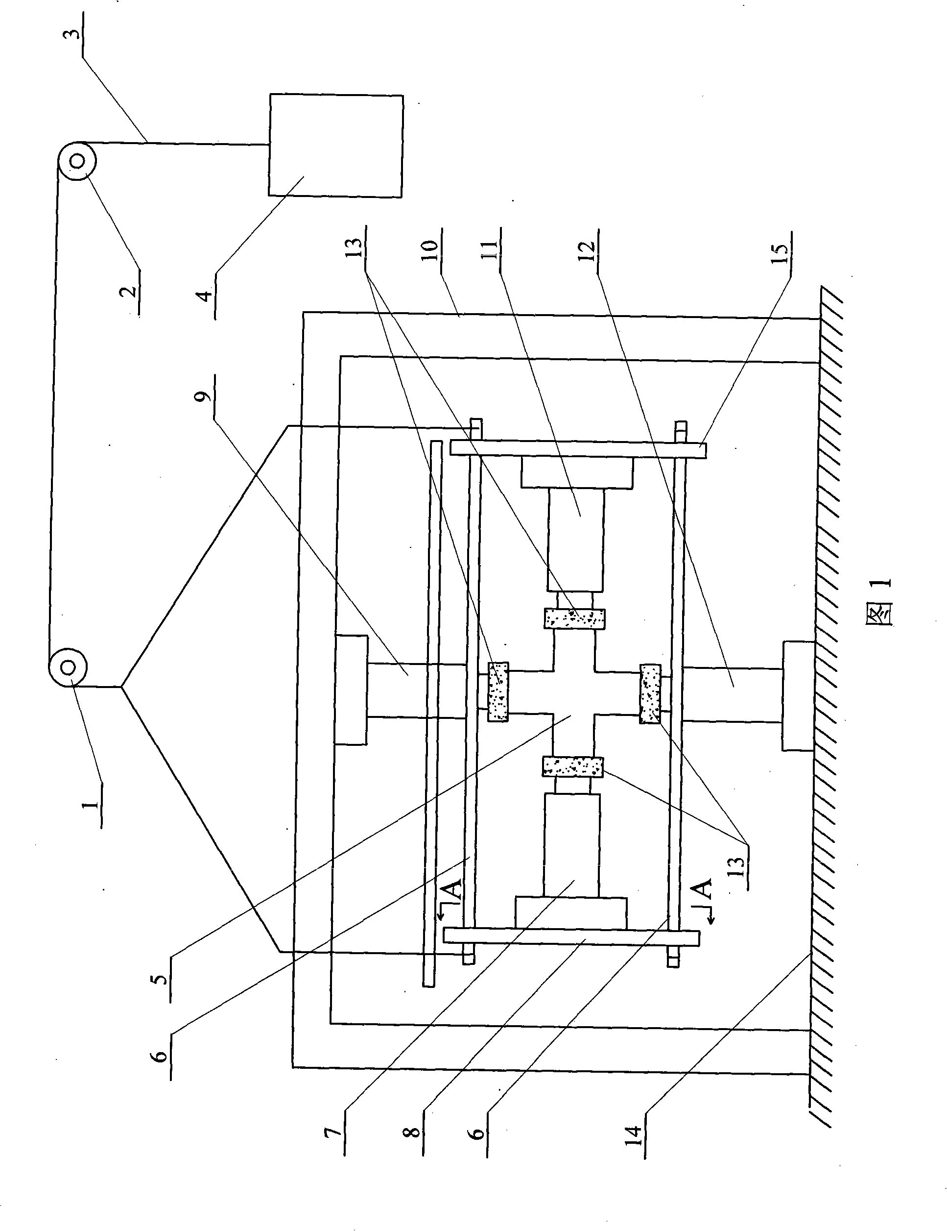
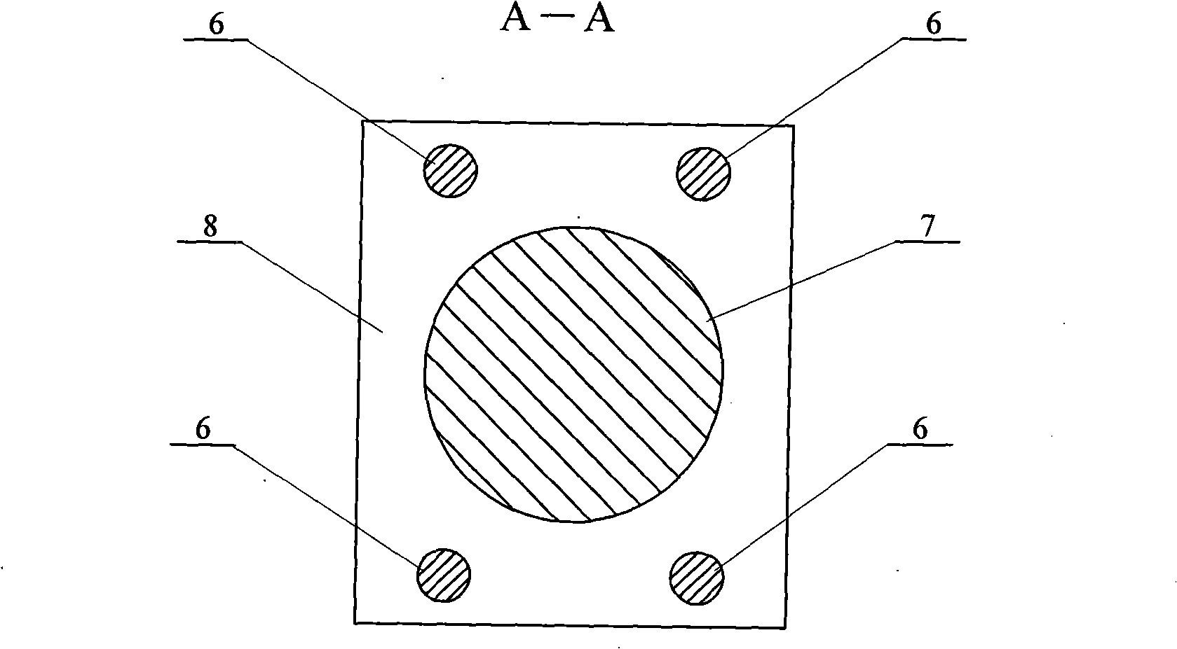
[0007] Specific embodiment one: (referring to Fig. 1 and figure 2 ) This embodiment consists of a first fixed pulley 1, a second fixed pulley 2, a steel wire rope 3, a counterweight 4, four screw rods 6, a first horizontal loader 7, a first steel plate 8, a first vertical loader 9, The reaction force frame 10, the second horizontal loader 11, the second vertical loader 12, four pressure bearing plates 13 and the second steel plate 15 are composed. The lower ends of both sides of the reaction force frame 10 are fixed on the ground 14, and the second vertical loader The loader 12 is fixed on the ground 14 of the center position in the reaction frame 10, the first vertical loader 9 is fixed on the lower side of the center position of the crossbeam of the reaction frame 10, the first vertical loader 9 and the second vertical The free ends of the loader 12 are arranged oppositely up and down and have the same axis. The first steel plate 8 and the second steel plate 15 are arranged ...

specific Embodiment approach 2

[0008] Embodiment 2: (see FIG. 1 ) The outer side of the first fixed pulley 1 in this embodiment, that is, the downward trajectory of the wire rope 3 is the same as the axes of the first vertical loader 9 and the second vertical loader 12 . Others are the same as in the first embodiment.

specific Embodiment approach 3

[0009] Specific implementation mode three: (see Figure 6 ) The pressure bearing plate 13 of this embodiment is composed of a base plate 17, a backing plate 18 and a sleeve 19. A convex spherical cap 16 is provided on one side of the base plate 17, and a convex spherical cap 16 is provided on the backing plate 18 to cooperate with the convex spherical cap 16. The concave surface 20 of the base plate 17 is arranged corresponding to the backing plate 18, and the backing plate 18 is connected with the sleeve 19. Concrete specimens are casted with steel molds, but sometimes the four loading surfaces of concrete specimens cannot be absolutely guaranteed to be perpendicular to each other, and it is impossible to ensure the absolute translation of the bearing plate during loading, so the pressure bearing plate of the concrete compression test is designed It is a spherical hinge support to accommodate rotation in two vertical directions. A convex spherical cap 16 is provided on the b...


PUM

PropertyMeasurementUnit
Section radiusaaaaaaaaaa

Abstract

The invention discloses a concrete plane complex stress test device, and relates to a concrete stress test device. The invention aims at solving the problem that when a concrete loading test is carried out by the existing multi-shaft testing loading equipment, the concrete transverse deformation is limited to result in friction, which causes a greater difference between the test result and the practical situation. In the device, a second vertical loader is fixed on the ground at the central position inside a reacting force frame, a first vertical loader is fixed on the underside of the central position of the reacting force frame beam, a first horizontal loader and a second horizontal loader are respectively fixed on the internal sides of a first steel plate and a second steel plate. The device can accomplish the concrete plane complex stress test which is a plane stress test of two-way stressing, two-way pulling, one-way stressing, one-way pulling, shear stressing and shear pulling. A hydraulic servo controls two mutually perpendicular loading directions by a control system and the loading speed and different two-way loading combinations can be adjusted automatically. The device can be used for a load control loading test and also for a deformation control loading test.

Description

technical field [0001] The invention relates to a concrete force test device. Background technique [0002] Practical concrete structures such as: shear and compression zones of reinforced concrete beams, joint zones of roof trusses and frame beams and columns, anchorage zones of post-tensioned steel bars, pipe columns, corbels, deep beams, wall panels and thin walls, etc. Components, as well as dams, high-pressure vessels of nuclear reactors, etc. are in a two-way and three-way complex force state. However, the concrete strength given by the general reinforced concrete structure design code is the concrete strength under multi-series unidirectional stress state, and the concrete strength, deformation and elastic modulus under complex stress state are all the same as those under unidirectional stress state. Different, the damage mechanism is not the same. Therefore, it is particularly important to develop concrete multiaxial loading equipment under complex stress condition...

Claims


Application Information

Patent Timeline
IPC IPC(8): G01N3/00G01M19/00G01M99/00
Inventor 董毓利王勇张大山吕俊利杨志年
Owner HARBIN INST OF TECH
Why Eureka
Try Eureka