Linear-motion actuator

A linear actuator, axis direction technology, applied in the direction of electric components, casing/cover/support, control mechanical energy, etc., can solve the problem of size increase, and achieve the effect of reducing size

Inactive Publication Date: 2009-04-15
SANKYO SEIKI MFG CO LTD
View PDF1 Cites 10 Cited by
  • Summary
  • Abstract
  • Description
  • Claims
  • Application Information

AI Technical Summary

Problems solved by technology

That is, the anti-rotation mechanism part and the guide part whose length corresponds to the stroke amount of the output shaft have to be provided along the output shaft, and there is a problem that the size of the linear actuator in the direction of the output shaft increases.

Method used


Image

  • Linear-motion actuator
  • Linear-motion actuator
  • Linear-motion actuator

Examples


Embodiment Construction

[0042] Embodiments of the linear actuator of the present invention will be described in detail below with reference to the drawings.

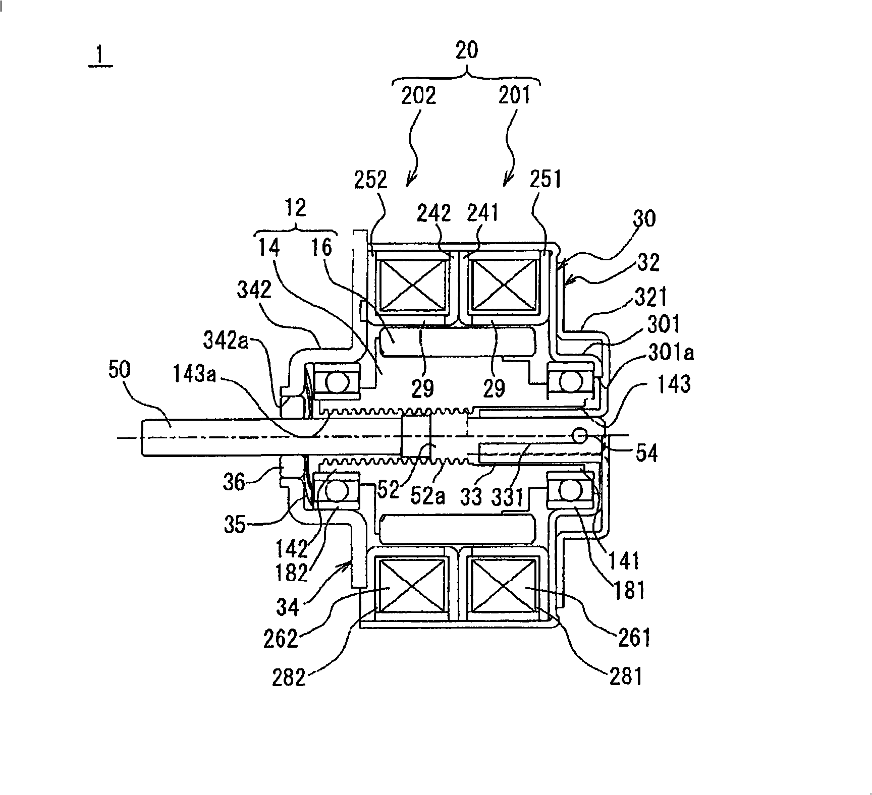
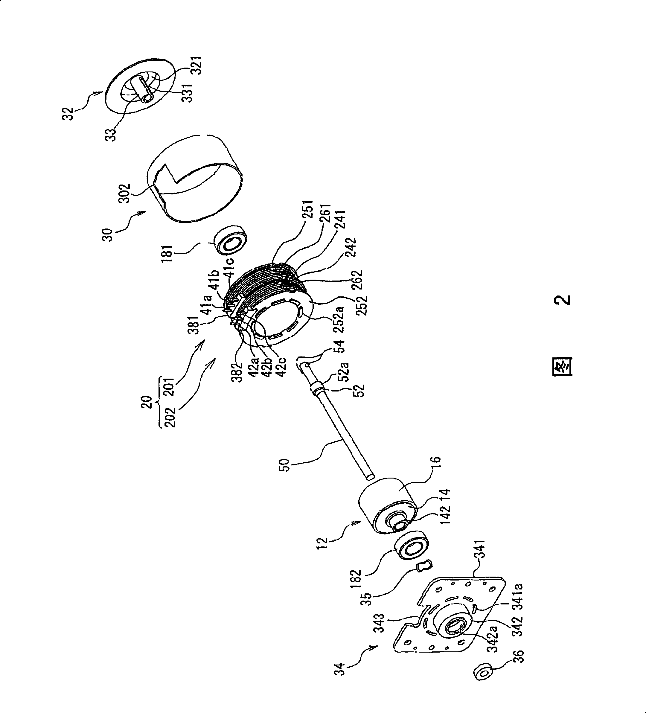
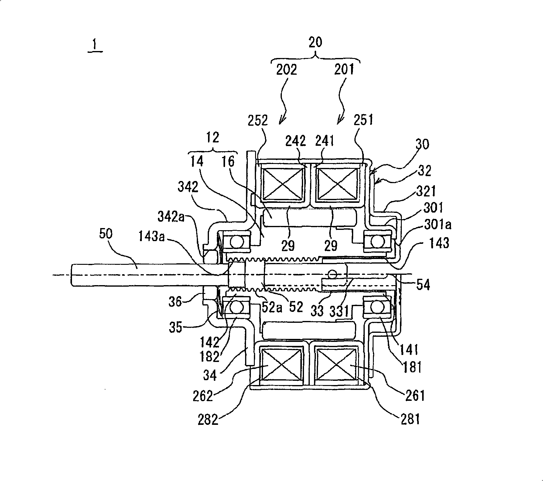
[0043] figure 1 is a sectional view of the linear actuator 1 according to the first embodiment of the present invention, and FIG. 2 is an exploded perspective view of the linear actuator 1 . In this linear actuator 1, the output shaft 50 moves forward and backward along the axial direction with a predetermined stroke amount ( figure 1 Actuator that advances to the left and backs to the right). In the following description, the axial direction in which the output shaft 50 protrudes ( figure 1 The left side of the middle) is called the output side, and the opposite axis direction ( figure 1 The right side in the center) is called the anti-output side.

[0044] The linear actuator 1 of this embodiment includes: a fixed-side member 30 having a stator 20 , a rotor 12 supported so as to be rotatable about an axis relative to the fixed-side member...


PUM


Abstract

A linear-motion actuator includes a fixed side member, a rotor rotatably supported by the fixed side member, and an output shaft disposed on an inner side of the rotor and movable in an axial direction. The linear-motion actuator may further include a rotation-linear motion converting mechanism which is provided with a turning prevention means for restricting rotation of the output shaft and which converts rotation of the rotor into a linear motion in the axial direction of the output shaft. The fixed side member may include a tubular member which accommodates a part of the output shaft and guides the output shaft for movement in the axial direction, and the turning prevention means may include an engagement part formed on the output shaft and a restriction part formed on an inner peripheral face of the tubular member and engaged with the engagement part.

Description

technical field [0001] The invention relates to a linear actuator, in particular to a linear actuator which converts the rotary motion of a rotor into the linear motion of an output shaft and then outputs it. Background technique [0002] As a linear actuator that outputs a rotational motion of a rotor as a linear motion of an output shaft, there is a linear actuator described in Patent Document 1, for example. This linear actuator is configured by screwing an output shaft with a male thread formed on the outer peripheral surface with a female thread formed on the inner peripheral surface of a rotating rotor. [0003] Patent Document 1: Japanese Patent Laid-Open No. 10-322963 [0004] In general, this type of linear actuator requires a detent mechanism that prevents the output shaft from rotating when the rotor rotates. In addition, a guide portion for guiding the output shaft when the output shaft advances and retreats is also required. That is, the anti-rotation mechani...

Claims


Application Information

Patent Timeline
Patent Type & Authority Applications(China)
IPC IPC(8): H02K7/06H02K5/16
CPCH02K7/06H02K2201/18H02K7/003
Inventor 内海信一
Owner SANKYO SEIKI MFG CO LTD
Why Eureka
Try Eureka