An electrical machine having a stator with rectangular and trapezoidal teeth

A stator and generator technology, applied in electric components, electromechanical devices, electrical components, etc., can solve the problems of increased motor manufacturing cost and complex motor structure, and achieve the goals of reducing the number of parts, improving heat transfer, and reducing copper loss Effect

Inactive Publication Date: 2009-04-15
SMART MOTOR AS
View PDF6 Cites 13 Cited by
  • Summary
  • Abstract
  • Description
  • Claims
  • Application Information

AI Technical Summary

Problems solved by technology

The disadvantage of the above two methods is that the structure of the motor is complicated, thereby increasing the manufacturing cost of the motor

Method used


Image

  • An electrical machine having a stator with rectangular and trapezoidal teeth
  • An electrical machine having a stator with rectangular and trapezoidal teeth
  • An electrical machine having a stator with rectangular and trapezoidal teeth

Examples


Embodiment Construction

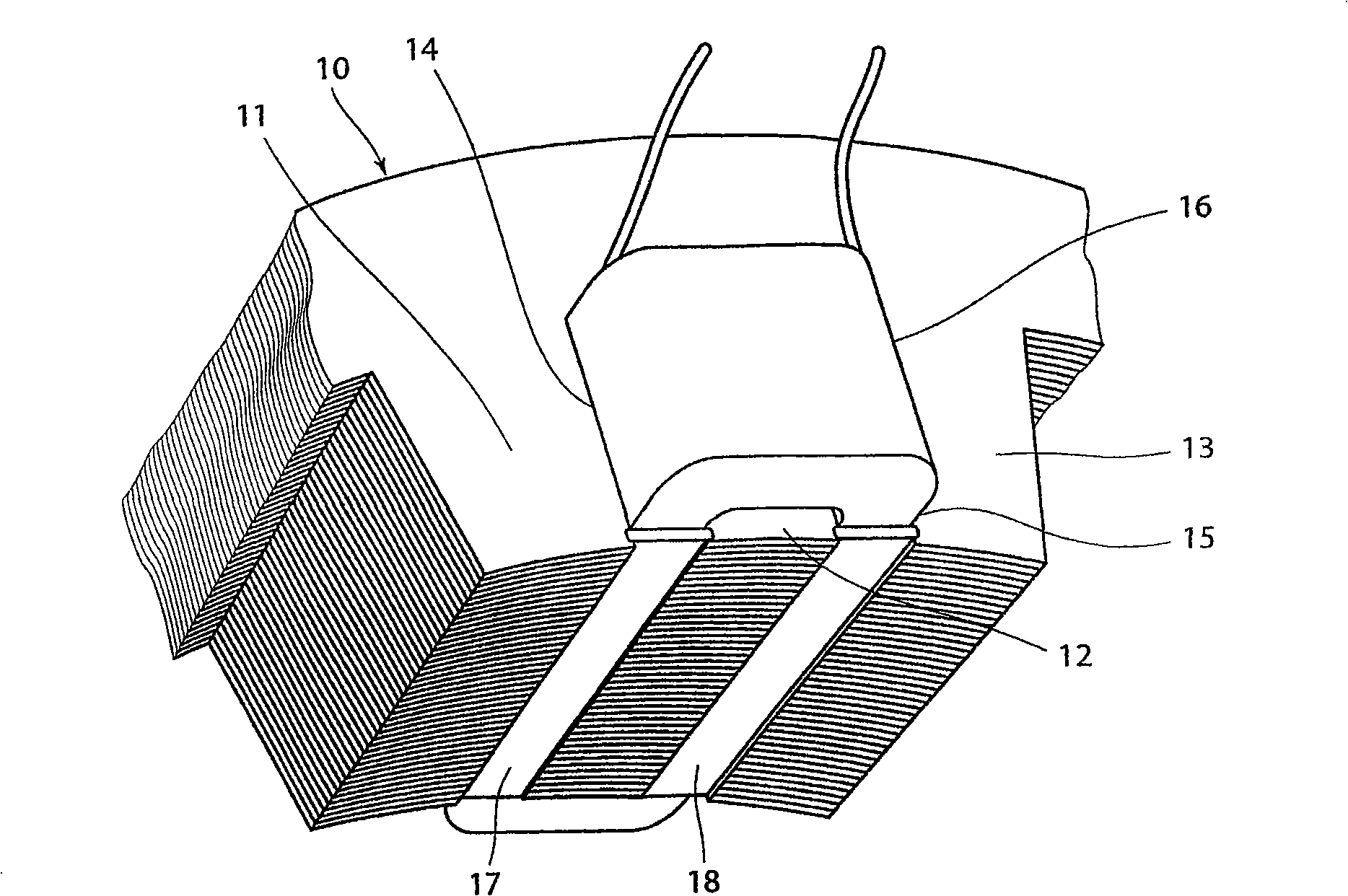
[0032] figure 1 A stack of stator laminations 1d is shown with teeth 11 , 12 , 13 forming slots 14 , 15 for receiving coils 16 . Each second tooth 12 is a parallel tooth and accommodates a coil 16 with the same opening and the same winding. as reference image 3 As stated, the grooves in this example are closed by wedges 17,18.

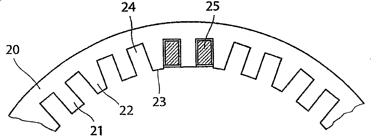
[0033] figure 2 Another embodiment of a stator lamination 20 for making an outer stator is shown. The rotor of the electric machine may be of prior art design and is not shown. The stator laminations 20 have alternately arranged parallel teeth 21 and trapezoidal teeth 22 that taper outwards towards the tooth tips 23 . Therefore, pairs of parallel slots 24 for insertion of prior art rectangular coils are provided. The width of adjacent teeth should be determined to optimize the voltage curve and detent torque. The teeth shown in this example have the same tip width. But the width can vary within a ratio of 0.9-1.1 to 1. The degree of constric...


PUM


Abstract

Arrangement at an electric machine, particularly motor, generator, or actuator, with a stator with teeth (11, 12) carrying coils (15), particularly one layer, for concentrated windings. A permanent magnetic rotor is movable relatively to the stator (11, 12). The teeth of the stator are arranged for receiving coils (15) with generally rectangular opening. Advantages are achieved if the stator teeth (11, 12) are provided to receive generally identical coils (15) closing the grooves (14, 16). The teeth (11, 12) may be alternating rectangular and converging/diverging toward the top, to provide grooves (14, 16), with parallel sides to enter the coils (15). The converging teeth (22) have preferably a shortened top (23). The grooves are preferably provided to make room for a semi magnetic groove wedge (17, 18) between adjacent teeth.

Description

[0001] technology field. [0002] The invention relates to an electric machine arrangement as stated in the preamble of claim 1 . The electric machine arrangement may be an electric motor or generator, or an actuator with an armature moving along a straight or arcuate path. As described in the examples, such an electric motor device can be manufactured in different sizes according to the purpose of use. Background technique [0003] Traditionally, electric machines are based on synchronous machines with field windings as well as asynchronous machines. In the last decade, the application of permanent magnet synchronous motors (PMSM) has increased. The cost of permanent magnets has come down as research and development on this type of motor has intensified. Today, PMSM motors are used in various fields, such as the paper industry, offshore and marine sector. PMSM motors have also become more popular in other fields where motors are used. [0004] Some of the aforementioned ...

Claims


Application Information

Patent Timeline
Patent Type & Authority Applications(China)
IPC IPC(8): H02K1/16
CPCH02K3/493H02K1/146
Inventor 弗雷德里克·伊德兰埃德加·勒弗里西格德·奥弗里博
Owner SMART MOTOR AS
Why Eureka
Try Eureka