Laser processing device and laser processing method

A technology for laser processing and processed objects, which is applied in laser welding equipment, metal processing equipment, installation, etc., and can solve problems such as the inability to use laser processing devices

Inactive Publication Date: 2009-04-22
OLYMPUS CORP
View PDF6 Cites 2 Cited by
  • Summary
  • Abstract
  • Description
  • Claims
  • Application Information

AI Technical Summary

Problems solved by technology

[0008] However, in the laser processing apparatus using the existing microlens array as described above, once the number of degraded elements increases and degraded elements are produced throughout the entire surface of the DMD, even if the microlens array is slid, sometimes the degraded elements cannot be avoided. For processing, the laser processing device will be stopped at this time, and the laser processing device cannot be used until the new microlens array is replaced. Therefore, for example, when the laser processing device is used in the production line of the processed object, the production line must be stopped. question

Method used


Image

  • Laser processing device and laser processing method
  • Laser processing device and laser processing method
  • Laser processing device and laser processing method

Examples


no. 1 Embodiment approach

[0048] The laser processing apparatus according to the first embodiment of the present invention will be described.

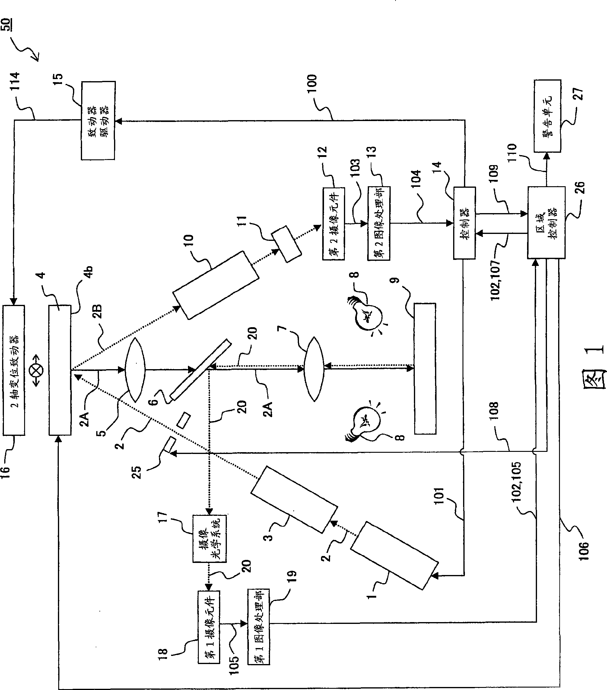
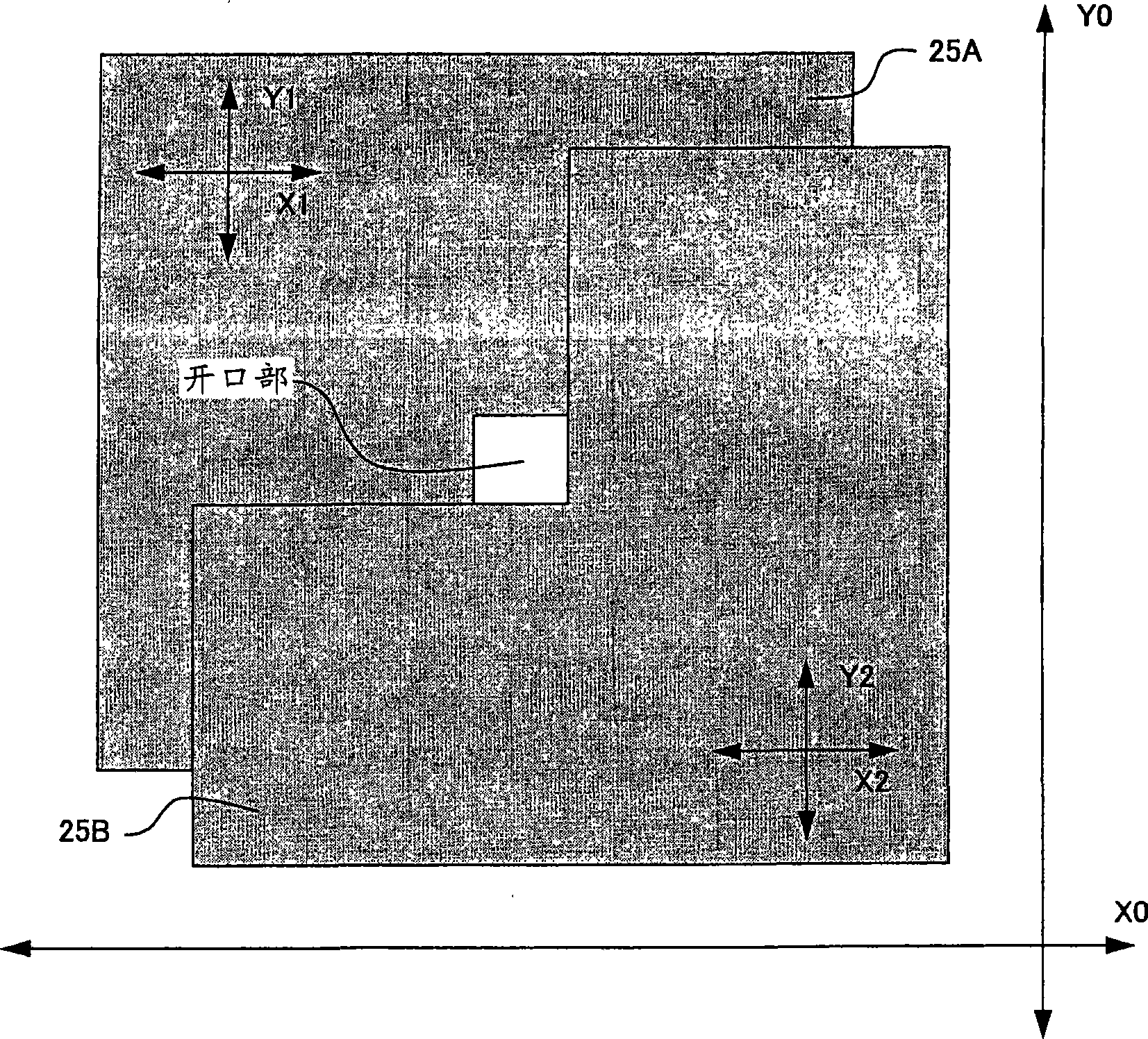
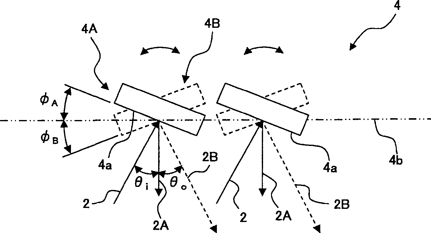
[0049] FIG. 1 is a schematic configuration explanatory diagram for explaining a schematic configuration of a laser processing apparatus according to a first embodiment of the present invention. figure 2 It is an explanatory drawing for demonstrating the structure of the slit of the laser processing apparatus concerning 1st Embodiment of this invention. image 3 It is a cross-sectional explanatory view for explaining the configuration and operation in the cross-sectional direction of the microlens array of the laser processing apparatus according to the first embodiment of the present invention. Figure 4It is a schematic plan explanatory view showing the microlens array of the laser processing apparatus according to the first embodiment of the present invention viewed from the reflective surface side, and a plan view showing an example of an image on a workpie...


PUM


Abstract

The invention relates to a laser processing device and laser processing method which can ensure the prescribed irradiating area for continuous use even under the condition of processing the object incapable of voiding tiny lenses with abnormal movement. The laser processing device comprises a space adjusting element comprises of a plurality of small movable elements for irradiating the object to be processed with laser beams from laser source in the predicted shape; an objecting optical system configured at the position conjugate with the space adjusting element and the object to be processed; an unit for controlling action of the space adjusting element according the irradiating area set before the irradiation; an unit detecting small movable elements with abnormal actions in the small movable elements which construct the space adjusting element; and an unit for controlling the areas having no detected abnormal actions to repeatedly irradiate the object to be processed when the position of the small movable elements having detected abnormal actions overlaps the irradiating area.

Description

technical field [0001] The present invention relates to a laser processing device represented by a digital micromirror device using a spatial modulation element such as a microlens array, and in particular to extracting a defect region on a substrate by imaging in the process of manufacturing a substrate such as a liquid crystal display device, according to the A laser correction device that corrects the shape of the defect area. Background technique [0002] Conventionally, there is known a laser processing apparatus that switches the laser beam irradiated to the workpiece by a plurality of microscopic mirrors, and performs processing by changing the range and pattern of the irradiated laser beam. [0003] In such a laser processing device, since a high-output laser beam is irradiated on the surface of a micro-lens having a small area, the micro-lens tends to deteriorate over time, and once the micro-lens deteriorates, for example, the mirror surface of the micro-lens is in...

Claims


Application Information

Patent Timeline
Patent Type & Authority Applications(China)
IPC IPC(8): B23K26/00B23K26/04G02B26/08G02B7/00G02B7/182B23K26/064B23K101/40
CPCB23K26/032B23K26/06B23K26/083B23K26/0869B23K26/50
Inventor 内木裕
Owner OLYMPUS CORP
Why Eureka
Try Eureka