
Bead feed mechanism of full-automatic charging and blanking switcher and bead feed method thereof

A fully automatic and transfer technology, which is applied in the direction of machine tools, grinding machines, metal processing equipment, etc., which are suitable for grinding the edge of workpieces, and can solve the problems of labor consumption, high replacement cost, and time-consuming

Inactive Publication Date: 2009-04-22
温州宏业精机有限公司
View PDF0 Cites 7 Cited by
  • Summary
  • Abstract
  • Description
  • Claims
  • Application Information

AI Technical Summary

Problems solved by technology

[0002] When the two upper bead boards are butted in the loading and unloading transfer machine of the traditional bead grinding and polishing machine, because the mold pin on one of the upper bead boards has welded the bead by welding powder, and the exposed surface of the bead After grinding and polishing, it is necessary to transfer and weld the bead embryo from the upper bead plate to the mold pin on another upper bead plate that is docked with it, so that the unpolished surface of the bead embryo can be ground and polished , at present, because the die pins on the upper bead board are arranged side by side, when transferring the bead embryo from one upper bead board to another upper bead board, occasionally the adjacent die pins that are closely side by side There is a phenomenon of bead embryo stacking between the bead embryos. If the bead embryos are directly connected to another upper bead board to transfer the bead embryos, the bead embryos stacked between the adjacent mold needles will damage the butt joints. Another mold needle on the upper bead plate caused damage to the mold needle, which not only affected the production efficiency of the complete set of equipment for the bead grinding and polishing machine, but also time-consuming, labor-intensive and expensive replacement of the mold needle

Method used


Image

  • Bead feed mechanism of full-automatic charging and blanking switcher and bead feed method thereof
  • Bead feed mechanism of full-automatic charging and blanking switcher and bead feed method thereof

Examples


Embodiment Construction

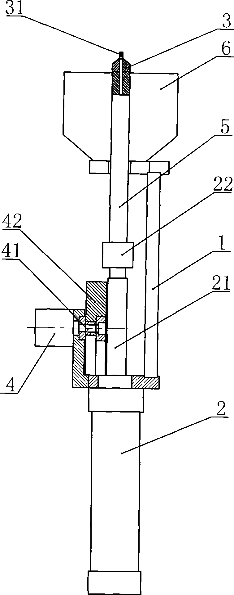
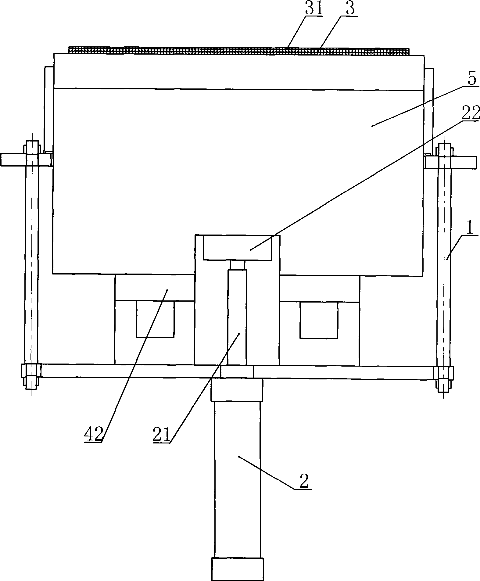
[0016] Such as Figure 1-2 The specific embodiment of the present invention shown comprises support 1, and the bottom of described support 1 is equipped with bead-feeding cylinder 2, and the upper end of described support is fixedly provided with holding box 6, and the piston rod of this bead-feeding cylinder 2 21 can move through the bottom of the bracket 1, and the piston rod 21 is provided with an upper bead plate 3 linked with it, the upper bead plate 3 can move through the bottom of the material box 6, the upper bead plate 3 Die pins 31 are fixed side by side on the upper side. In addition, the bracket 1 described in this embodiment is provided with a vibration bead cylinder 4 facing the side wall of the piston rod 21 of the bead delivery cylinder 2. The piston rod 41 of the vibration bead cylinder 4 The head end is fixedly provided with a vibration plate 42, and the upper end of the described bead delivery cylinder piston rod 21 is fixedly provided with a vibration block...


PUM


Abstract

The invention discloses a bead feeding mechanism of a fully-automatic loading and unloading switcher and a bead feeding method thereof. The bead feeding mechanism comprises a bracket, the upper end of the bracket is fixedly provided with a receiving box, the bottom of the bracket is provided with a bead feeding cylinder, a piston rod of the bead feeding cylinder is provided with a bead loading plate linked and matched with the bead feeding cylinder, the bead loading plate can movably pass through the bottom of the receiving box, and the bead loading plate is fixedly provided with a die needle side by side, the bracket is provided with a vibratory bead cylinder opposite to the side wall of the piston rod of the bead feeding cylinder, the head end of a piston rod of the vibratory bead cylinder is fixedly provided with a vibrating plate, and the piston rod of the bead feeding cylinder relative to the upper end of the vibrating plate is fixedly provided with a vibrating block which is clamped and matched with the vibrating plate in the extending direction of the piston rod of the bead feeding cylinder. The bead feeding mechanism has the advantages of good stability, low failure rate, high production efficiency, and the like.

Description

technical field [0001] The invention relates to a fully automatic loading and unloading transfer machine, in particular to a bead feeding mechanism and a bead feeding method of a fully automatic loading and unloading transfer machine. Background technique [0002] When the two upper bead boards are butted in the loading and unloading transfer machine of the traditional bead grinding and polishing machine, because the mold pin on one of the upper bead boards has welded the bead by welding powder, and the exposed surface of the bead After grinding and polishing, it is necessary to transfer and weld the bead embryo from the upper bead plate to the mold pin on another upper bead plate that is docked with it, so that the unpolished surface of the bead embryo can be ground and polished , at present, because the die pins on the upper bead board are arranged side by side, when transferring the bead embryo from one upper bead board to another upper bead board, occasionally the adjace...

Claims


Application Information

Patent Timeline
IPC IPC(8): B24B9/16
Inventor 张岳恩
Owner 温州宏业精机有限公司
Learn More