
Accumulation mounting method for cable sky dome tower frame raising cable rod

An installation method and lifting cable technology are applied to the structure of the dome, the roof, building components, etc., which can solve the problems of reducing the ridge cable, fixing it unchanged, and increasing the workload of installation at high altitude, so as to reduce the distance of traction and facilitate Position and tension, reduce the effect of construction difficulty

Inactive Publication Date: 2010-07-07
SOUTHEAST UNIV
View PDF0 Cites 0 Cited by
  • Summary
  • Abstract
  • Description
  • Claims
  • Application Information

AI Technical Summary

Problems solved by technology

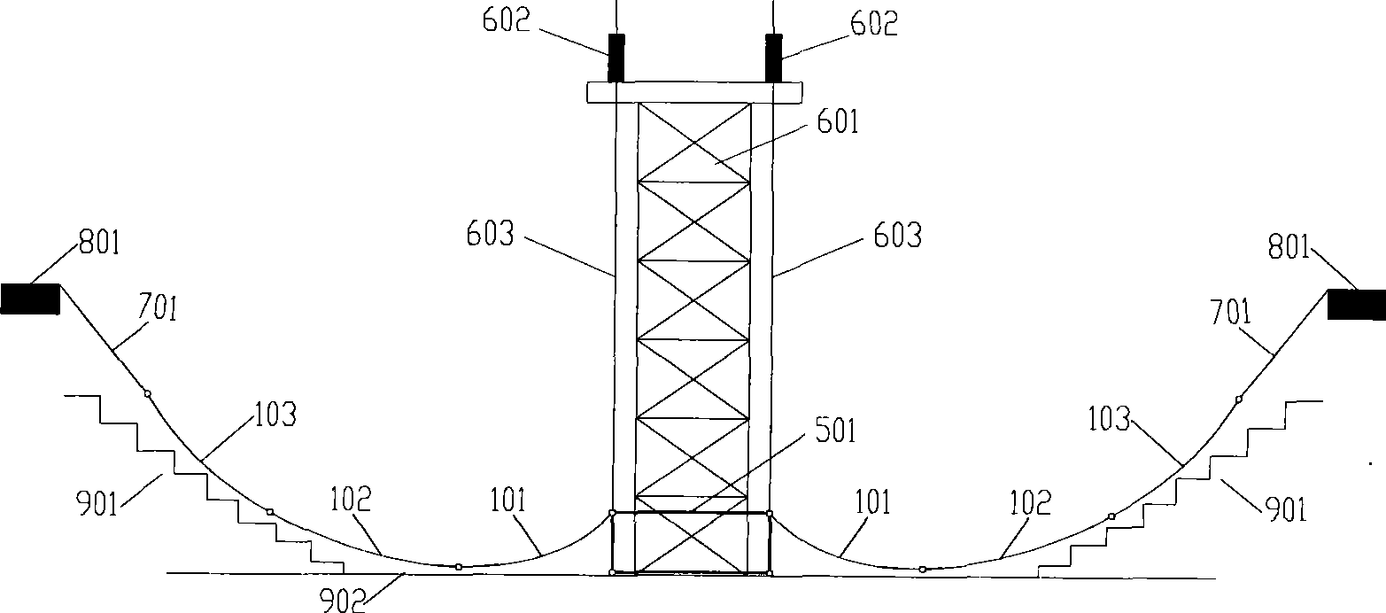
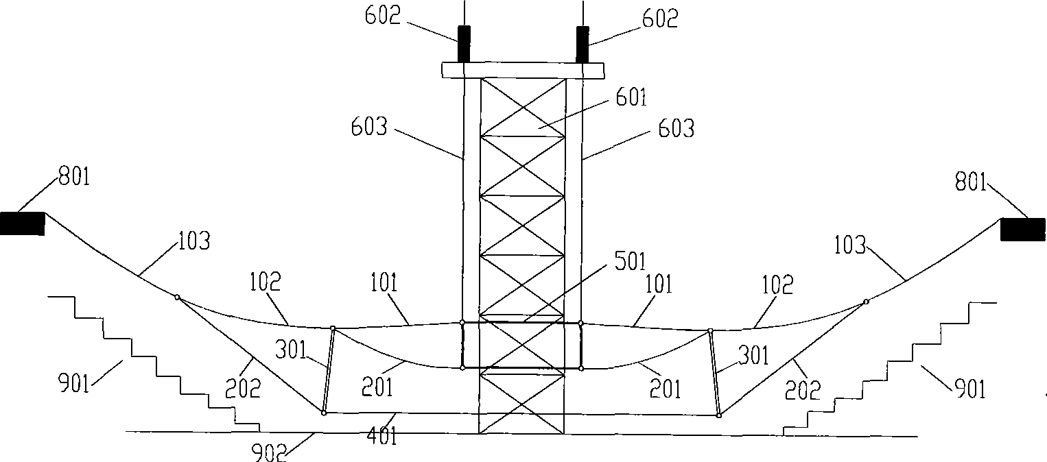
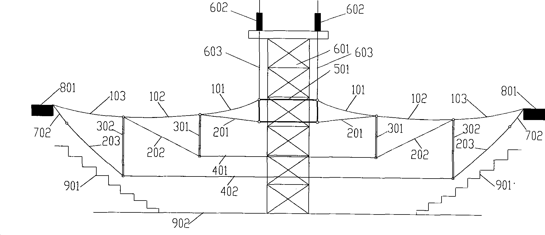
[0003] Technical problem: In order to overcome the difficulty and increased traction force of the ridge cable and oblique cable in the construction of the existing cable dome structure, the support height of the central load-bearing member is fixed, resulting in an increase in the amount of high-altitude work for the ring-by-ring cable rod installation. Unfavorable factors such as increased construction safety risks, the present invention proposes a cumulative installation method for hoisting cable rods of cable dome towers, which can not only reduce the distance and difficulty of ridge cable traction, but also expand and install each The ring cable rod can adjust the support height of the central load-bearing member at will, which is convenient for the installation and traction tension of the cable rod at different height points, so that the installation and construction difficulty of the cable dome structure is significantly reduced, and the installation and construction process of the cable rod is increased. safety

Method used


Image

  • Accumulation mounting method for cable sky dome tower frame raising cable rod
  • Accumulation mounting method for cable sky dome tower frame raising cable rod
  • Accumulation mounting method for cable sky dome tower frame raising cable rod

Examples


Embodiment Construction

[0024] In the present invention, according to the design elevation of the cable dome and the corresponding position of the central force-bearing member, a lifting tower slightly higher than the design elevation of the apex of the cable dome is set up to uniformly lift the central force-bearing member. At the same time, the entire ridge cable network is also lifted, and then the expansion and cumulative installation of each ring cable, mast and diagonal cable is carried out. The installation sequence of the cable rods can be adjusted according to the distance from the ground or the step surface of each installation point. The height is adjusted, and after all the cables and masts are installed, the outermost ring cable is stretched and formed in stages.

[0025] Specifically, the central load-bearing member 501 is placed on the ground in the center of the site, and the lifting tower 601 and lifting equipment 602 are installed. At the same time, the outer ring ridge cable 103, th...


PUM


Abstract

The invention discloses a method for cumulatively mounting a cable dome tower lifting cable rod, which comprises the following steps: mounting a lifting tower slightly higher than the mounting height of the vertex of a cable dome structure according to the design elevation of a cable dome and a corresponding position of a central bearing member; mounting a multipoint synchronous lifting device onthe top of the tower; connecting an inner ring cable system of a notochord net with the central bearing member and connecting an outer ring cable system of the notochord net with an outer ring beam through auxiliary traction cables; evenly lifting the central bearing member through a lifting device on the top of the tower with the traction of an outer ring notochord and the lifting of the centralbearing member in the lifting process, wherein the whole notochord net is lifted synchronously in a catenary mode; cumulatively and expansively mounting each ring cable, masts and stay cables positioned at different mounting heights while lifting the central bearing member; and after all the traction cables and the masts are mounted, forming outer ring stayed cables through tensioning by stages.

Description

technical field [0001] The invention relates to a method for installing cable rods and prestressed tension forming for the construction of a new cable dome space tension structure in civil engineering construction. The utility model belongs to the technical field of cable dome structure construction and installation. Background technique [0002] The cable dome structure is a new type of full-tension structure system, which consists of the ridge cable on the upper chord, the oblique cable on the lower chord, and the mast connecting the upper and lower chord cables. Stable bearing system. The stay cable can be in various forms such as semi-parallel twisted high-strength steel strands, multiple steel strands assembled cables, or steel rod rods. The main steps of the cable dome structure installation and forming method known both at home and abroad are: (1) placing the central load-bearing member; (2) hanging the ridge cable, one end is connected with the outer ring beam, and...

Claims


Application Information

Patent Timeline
Patent Type & Authority Patents(China)
IPC IPC(8): E04B1/32E04B1/35E04B7/08
Inventor 郭正兴宗钟凌罗斌王永泉
Owner SOUTHEAST UNIV
Learn More