Novel microwave rotary joint

A technology of rotary joints and microwaves, applied in waveguide devices, electrical components, circuits, etc., can solve the problems of narrow frequency band, small diameter of coaxial inner conductor, and inapplicability, achieve wide frequency band, ensure realizability, and ensure stability sexual effect

Active Publication Date: 2009-04-22
中国航天科技集团公司第五研究院第五〇四研究所
View PDF0 Cites 35 Cited by
  • Summary
  • Abstract
  • Description
  • Claims
  • Application Information

AI Technical Summary

Problems solved by technology

The disadvantage of the above two rotary joints is that the former solution is only suitable for low-frequency components because there are choke slots on the coaxial inner and outer conductors, and it is not suitable for the Ka frequency band. This is because In the Ka-band rotary joint, the diameter of the coaxial inner conductor is small, and it is difficult to process the choke groove on the inner conductor
The latter scheme uses the circular waveguide as the rotating part, and the high-order mode TM01 mode in the circular waveguide must be used as the transmission mode. The disadvantage of this scheme is that the frequency band is narrow

Method used


Image

  • Novel microwave rotary joint
  • Novel microwave rotary joint
  • Novel microwave rotary joint

Examples


Embodiment Construction

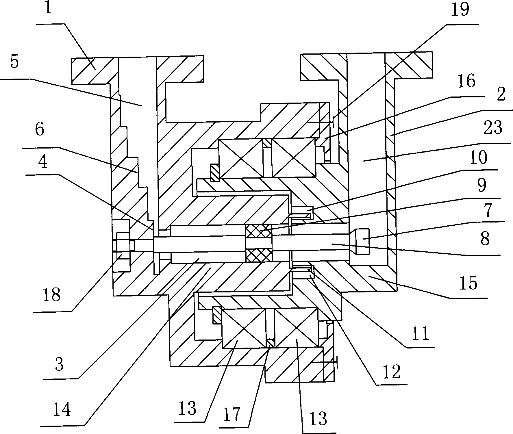
[0025] Such as figure 1 As shown, the present invention includes two waveguide coaxial converters, waveguide coaxial converter one 1 and waveguide coaxial converter two 2, and the two waveguide coaxial converters all include rectangular waveguides and are installed on the rectangular waveguide width The coaxial structure on the side axis, the coaxial structure of the two waveguide coaxial converters is the same coaxial axis 3 and the two rotate around the coaxial axis 3, the coaxial axis 3 is the same as the two waveguides The impedances of the rectangular waveguides of the axis converters are all matched. That is to say, the central axis of the coaxial line 3 is located on the central axis of the first broadside of the rectangular waveguide and the central axis of the second broadside of the rectangular waveguide. Wherein, the coaxial cable 3 includes a coaxial inner conductor 8 and two coaxial outer conductors which are sleeved on the outside of the coaxial inner conductor ...


PUM


Abstract

The invention relates to a novel microwave rotary joint which comprises two wave guide coaxial converters, and both of the wave guide coaxial converters comprise a rectangular wave guide and coaxial structure, and the coaxial structure is arranged on a broad side axis line of the rectangular wave guide; the coaxial structure of the two wave guide coaxial converters has the same coaxial line and both of the wave guide coaxial converters are rotated around the coaxial line; the coaxial line is matched with impedances of the two rectangular wave guides; the coaxial line comprises a coaxial inner conductor and two coaxial outer conductors; a support medium is arranged between the coaxial outer conductors and the coaxial inner conductor; a ridge wave guide is arranged in the rectangular wave guide of the wave guide coaxial converter one; one end of the coaxial inner conductor is extended into a rectangular wave guide cavity one and is fixed on the ridge wave guide; the ridge wave guide and the rectangular wave guide one are transformed and transmitted through a multi-stage ladder; the other end of the coaxial inner conductor is extended into a rectangular wave guide cavity two and is not contacted with the wave guide wall; the other end of the coaxial inner conductor is provided with a matched end head; and a buckling position of the two coaxial outer conductors is provided with a choke groove. The novel microwave rotary joint has broad bandwidth and good and stable performance, and is suitable for every frequency band from L to Ka.

Description

technical field [0001] The invention relates to the technical field of microwave components, in particular to a novel microwave rotary joint. Background technique [0002] With the rapid development of microwave technology, the application frequency band has gradually extended from L, S, and C frequency bands to higher frequency bands. At present, the application of Ka frequency band has become more and more extensive. Ka-band components have the characteristics of small size and high precision requirements, but the existing rotary joint scheme and its structure can no longer meet the requirements. Specifically, the existing rotary joints can be divided into two types: one is the coaxial axis as the rotating part, both ends of the coaxial inner conductor are connected with the waveguide wall, and the coaxial inner and outer conductors are designed with choke The two slots are broken into two parts at the choke slot to realize the rotation; the other is the circular waveguid...

Claims


Application Information

Patent Timeline
Patent Type & Authority Applications(China)
IPC IPC(8): H01P1/06
Inventor 李荣军杨慧杰许智张文会
Owner 中国航天科技集团公司第五研究院第五〇四研究所
Why Eureka
Try Eureka