
Method, system and apparatus managing alarm of long-distance passive optical network system

A passive optical network and alarm management technology, which is applied in the field of alarm management in long-distance PON systems, can solve the problem of inability to analyze and locate intermediate nodes, not providing long-distance PON signal transmission quality, and not providing LR-PON signal monitoring and alarm indication Problems such as handling methods to achieve the effect of convenient maintenance of equipment

Inactive Publication Date: 2009-04-22
GLOBAL INNOVATION AGGREGATORS LLC
View PDF0 Cites 28 Cited by
  • Summary
  • Abstract
  • Description
  • Claims
  • Application Information

AI Technical Summary

Problems solved by technology

[0007] Although the use of electrical relay regenerators can successfully extend the distance of the PON and meet the requirements of the LR-PON system for the coverage radius of the OLT, when the optical fiber transmission distance is extended from 20 kilometers to 100 kilometers, it will inevitably introduce long-distance optical fiber faults, and The introduction of active electrical relay equipment in the PON will also reduce the stability and reliability of the equipment in the system. The difficulty of fault location
However, although the existing PON system has complete monitoring and maintenance functions, and has detailed regulations on various alarm indications, performance events and management between the OLT and ONU, it is only applicable to the OLT and ONU in the traditional PON system. The situation where ONUs are directly interconnected by optical signals
In the application of electrical relay LR-PON, the necessary monitoring and processing of PON signals has not been carried out in the electrical relay regenerator at present. In the past, the alarm indication and maintenance functions only had transparent transmission, and it was impossible to analyze and locate the fault of the intermediate node.
It can be seen that in the proposed electrical relay LR-PON scheme, the problem of monitoring the transmission quality of long-distance PON signals has not been proposed, nor have various alarm indications and corresponding processing methods for LR-PON signal monitoring been proposed.

Method used


Image

  • Method, system and apparatus managing alarm of long-distance passive optical network system
  • Method, system and apparatus managing alarm of long-distance passive optical network system
  • Method, system and apparatus managing alarm of long-distance passive optical network system

Examples


Embodiment 1

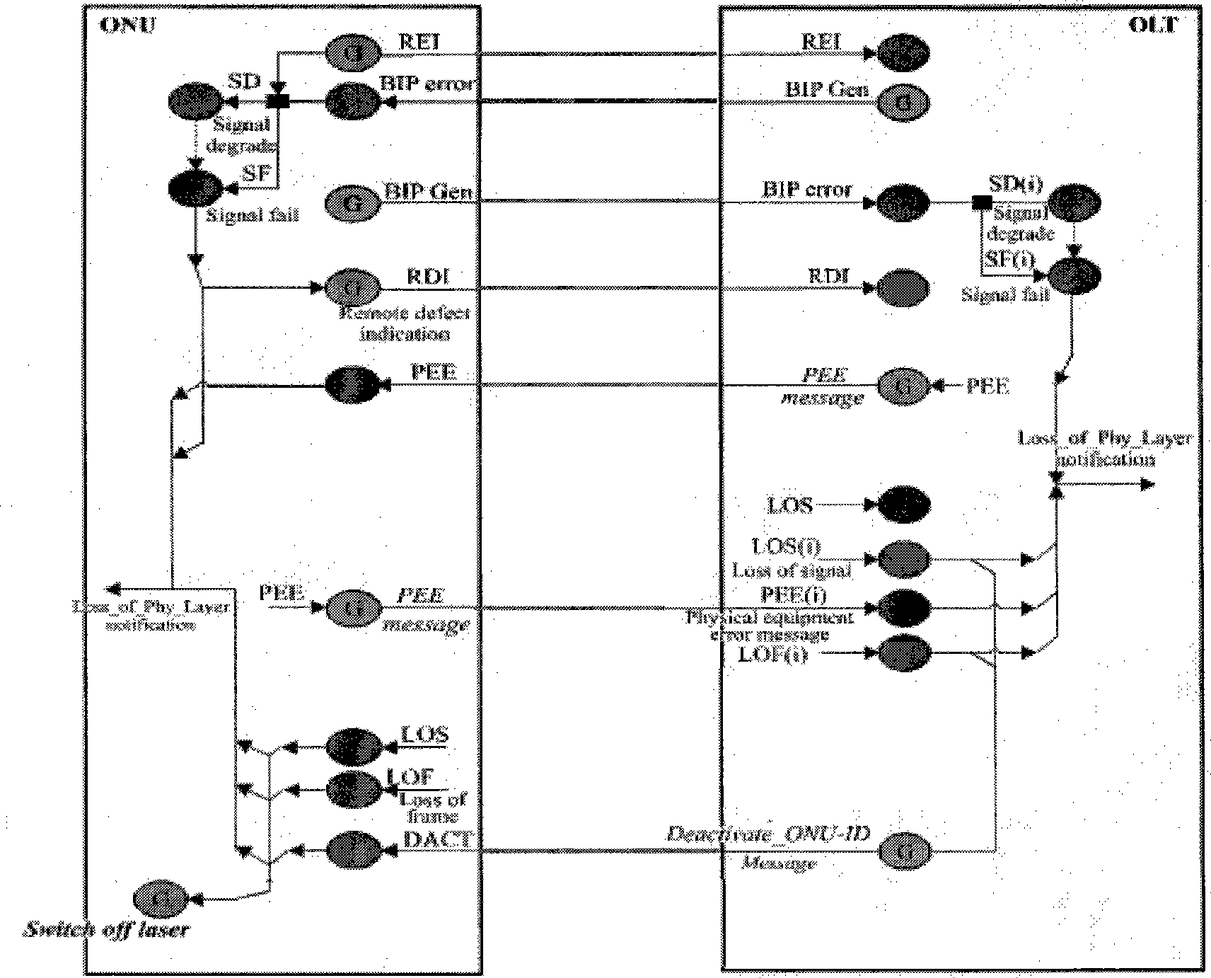
[0052] see Figure 4 , Figure 4 It is a schematic diagram of an alarm link according to an embodiment of the present invention. In this embodiment, only some alarm detection functions are added to the electrical relay regenerator, and no changes are made to the ONU and the OLT.

[0053] Down direction:

[0054] After the electrical relay regenerator detects the LOS and LOF alarms, it turns off the transmitting laser in the downlink direction, which causes the ONU to detect the LOS alarm in the downlink direction. There is a failure in the downstream path to the ONU that causes signal loss. When the electrical relay regenerator receives and clears the LOS and LOF alarms, it restarts the transmitting laser in the downlink direction.

[0055] Up direction:

[0056] After the electrical relay regenerator detects the LOS alarm, it turns off the transmitting laser in the uplink direction, which causes the OLT to detect the LOS alarm in the uplink direction, and the subsequent ...

Embodiment 2

[0061] see Figure 5 , Figure 5 It is a schematic diagram of an alarm link in Embodiment 2 of the present invention. In this embodiment, compared with Embodiment 1, an alarm return function is added to the electrical relay regenerator; three types of alarm detection and processing are added to the OLT to facilitate fault judgment and location; no changes are made to the ONU.

[0062] Down direction:

[0063] After the electrical relay regenerator detects the LOS and LOF alarms, it turns off the transmitting laser in the downlink direction. The details are the same as those described in Embodiment 1 and will not be repeated here.

[0064] After the electrical relay regenerator detects the LOS and LOF alarms, it returns the correspondingly set third type of downlink alarm indication signal to the OLT, where the third type of downlink alarm indication signal is RDIu;

[0065] After receiving the RDIu alarm, as shown in Table 1 above, the OLT determines that the downlink path ...

Embodiment 3

[0077] see Figure 7 , Figure 7 It is a schematic diagram of an alarm link in Embodiment 3 of the present invention. In this embodiment, compared with the second embodiment, an alarm return function is added to the electrical relay regenerator; two new alarm detection and processing are added to the ONU.

[0078] Down direction:

[0079] After the electrical relay regenerator detects the LOS and LOF alarms, it no longer turns off the transmitting laser in the downlink direction, but inserts the first type of downlink alarm indication signal to the ONU, and the first type of downlink alarm indication signal is AISd.

[0080] After receiving the AISd alarm, the ONU determines that the downlink path from the OLT to the electrical repeater regenerator has a fault that causes signal loss or frame loss; as shown in Table 3 above, the ONU suppresses the LOF alarm.

[0081] In the above steps, the down-insertion AISd alarm is a kind of "alarm frame", and its frame header can refer...


PUM


Abstract

The invention provides a warning management method in a long reach passive optical network (LR-PON) system, a system and a device thereof, wherein, the method comprises the steps as follows: a PON signal from one side of an optical line terminal (OLT) and an optical network unit (ONU) is obtained; whether the obtained PON signal has a failure or not is judged, if the obtained PON signal has the failure, the other side of the OLT and the ONU is informed. The method, the system and the device provided by the invention can realize the monitoring on LR-PON transmission quality and do corresponding treatment on various warning indications monitored by an LR-PON signal.

Description

technical field [0001] The present invention relates to passive optical network (PON, Passive Optical Network) technology, in particular to a method, system and device for alarm management in a long distance (LR, Long Reach) PON system. Background technique [0002] Currently, with the rise of video-on-demand, high-definition television, and online games, telecom users have increasingly demanding network bandwidth. Driven by this demand, the fiber-to-the-home (FTTH, Fiber to the Home) technology that can effectively guarantee the "last mile" access network has made great progress, among which the PON technology has been widely used. [0003] see figure 1 , figure 1 It is a structural schematic diagram of a traditional PON system. A traditional PON system includes an Optical Line Terminal (OLT, Optical Line Terminal), more than one Optical Network Unit (ONU, Optical Network Unit), and an Optical Distribution Network (ODN, Optical Distribution Network) that connects the ONU...

Claims


Application Information

Patent Timeline
Patent Type & Authority Applications(China)
IPC IPC(8): H04L12/26H04L1/00H04B10/08H04B10/12H04B10/079H04B10/272
CPCH04B10/07953H04B10/272H04J3/14H04Q2011/0081H04Q11/0067H04Q2011/0083H04L41/0677H04J3/1694H04B2210/08
Inventor 周建林邹世敏
Owner GLOBAL INNOVATION AGGREGATORS LLC
Learn More