
High performance hydraulic motor

A hydraulic motor, high-performance technology, applied in the field of hydraulic motors, can solve the problems of poor sealing performance, low output torque, low specific power, etc., and achieve the effect of easy processing, low cost and large torque

Inactive Publication Date: 2009-04-29
NINGBO HOYEA MACHINERY MFG +1
View PDF0 Cites 13 Cited by
  • Summary
  • Abstract
  • Description
  • Claims
  • Application Information

AI Technical Summary

Problems solved by technology

[0002] The structure of the existing vane hydraulic motor is that the rotor is eccentrically placed in the cylinder body, and the radial direction of the vane is placed in the rotor at a certain angle with the radius of the rotor. When working, the vane is thrown out under the action of the spring or oil pressure to form a seal with the cylinder body. Cavity, this type of vane hydraulic motor is sealed by a contact line between the vane and the cylinder body, so the sealing performance is poor, the output torque is low, and there is a lot of friction between the vane, the rotor and the cylinder body during rotation, As a result, the overall wear of the vane hydraulic motor is fast, the life is short, and the efficiency is low
In addition, in order to ensure that the blades can safely enter and exit the rotor during rotation, the rotor must have a considerable diameter, which is bound to be large in size and low in specific power.

Method used


Image

  • High performance hydraulic motor
  • High performance hydraulic motor
  • High performance hydraulic motor

Examples


Embodiment Construction

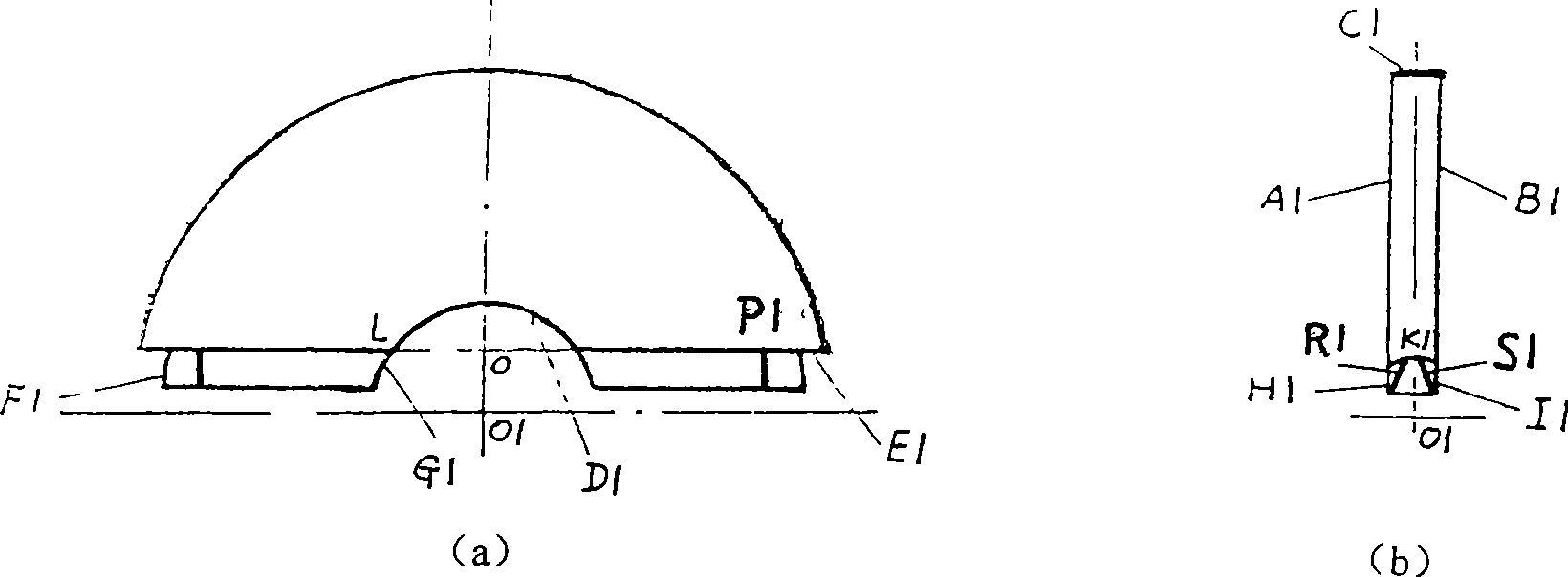
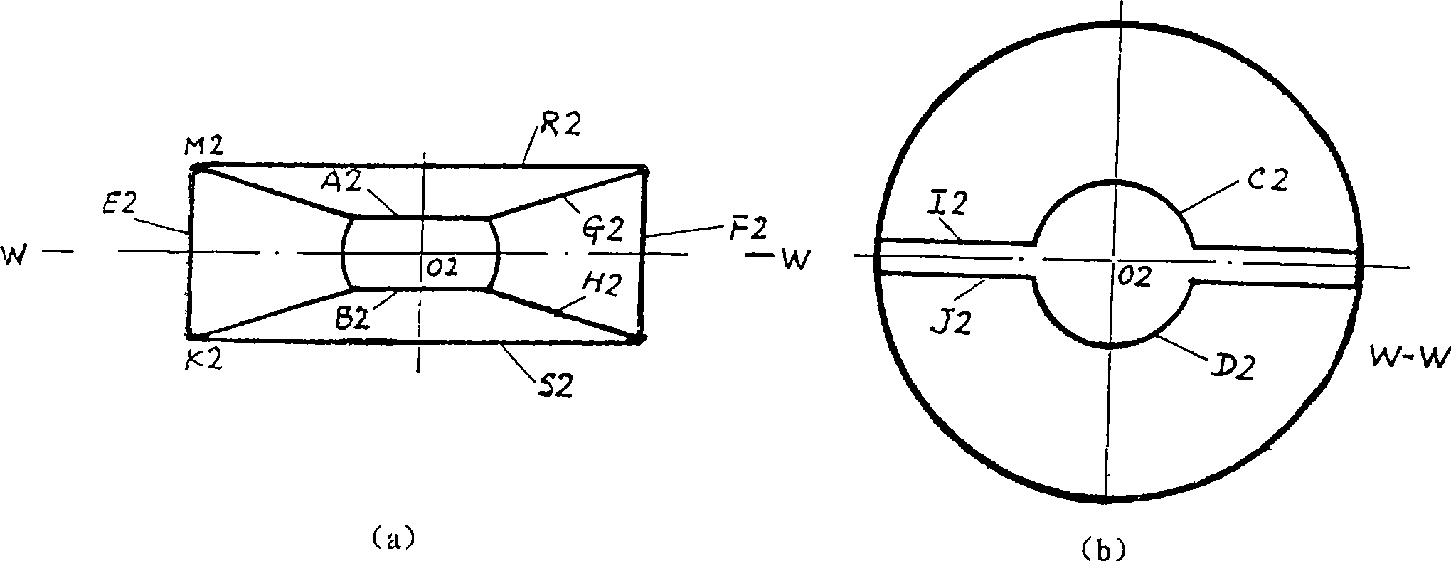
[0025] figure 1 a and figure 1 b shows the shape of the blade 3 and the sealing strip 4 of the present invention. The blade 3 is approximately semicircular, and there are two identical pieces. A1 and B1 are parallel planes. The width of the blade 3 is equal to the width of the hollow ring of the housing 1 in Figure 3b. Surface E3 is a cylindrical surface with the same radius, D1 is a spherical surface whose center of sphere is the same as O1 radius and rotor 2 ball table C2 radius, E1 is a cylindrical surface, and E1 cylindrical surface takes the symmetry axis passing through the center of sphere O1 as the central axis, and O1K1 as the radius.

[0026] There are four identical sealing strips 4, one of which has a cylindrical surface with a radius equal to that of the blade 3 cylindrical surface E1 on the upper side, and a plane on the lower side, and the vertical distance between the spherical center O1 and the plane is half of the thickness of the rotor 2 plate, G1 It is ...


PUM


Abstract

The invention discloses a high-performance hydraulic motor, which comprises a casing, a rotor, two blades, four sealing strips, and two cushion blocks. all the sealing places of the motor are surface sealing, and the motor has the advantages of large displacement, high pressure and efficiency, large specific power, compact structure, easy machining, lower cost and long service life.

Description

technical field [0001] The invention relates to a hydraulic motor, in particular to an overall scheme design of a novel high-performance vane hydraulic motor. Background technique [0002] The structure of the existing vane hydraulic motor is that the rotor is eccentrically placed in the cylinder body, and the radial direction of the vane is placed in the rotor at a certain angle with the radius of the rotor. When working, the vane is thrown out under the action of the spring or oil pressure to form a seal with the cylinder body. Cavity, this type of vane hydraulic motor is sealed by a contact line between the vane and the cylinder body, so the sealing performance is poor, the output torque is low, and there is a lot of friction between the vane, the rotor and the cylinder body during rotation, As a result, the overall wear of the vane hydraulic motor is fast, the life is short, and the efficiency is low. In addition, in order to ensure that the blades can safely enter and ...

Claims


Application Information

Patent Timeline
IPC IPC(8): F03C2/00F04C2/344F15B15/08
Inventor 陈行
Owner NINGBO HOYEA MACHINERY MFG
Features
  • Generate Ideas
  • Intellectual Property
  • Life Sciences
  • Materials
  • Tech Scout
  • Unparalleled Data Quality
  • Higher Quality Content
  • 60% Fewer Hallucinations
Learn More