
Heat exchange method of pipe shell type heat-exchanger and heat exchanger thereof

A shell-and-tube heat exchanger, heat method technology, applied in indirect heat exchangers, heat exchanger types, evaporators/condensers, etc., to save costs, reduce fouling deposits, and reduce energy consumption

Inactive Publication Date: 2009-04-29
广州联合冷热设备有限公司
View PDF0 Cites 4 Cited by
  • Summary
  • Abstract
  • Description
  • Claims
  • Application Information

AI Technical Summary

Problems solved by technology

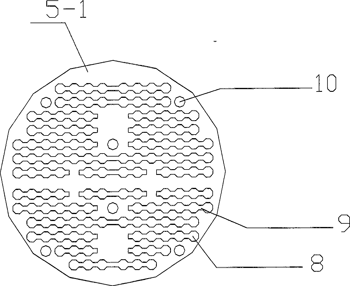
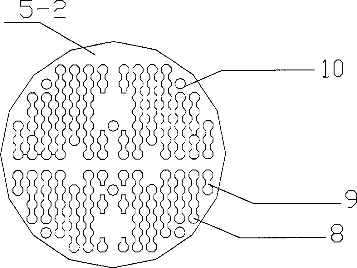
[0004] Aiming at the deficiencies in the existing heat exchanger manufacturing and heat exchange methods in the market, the present invention aims to provide a method that can make the shell side fluid flow in a more reasonable form, increase the average flow rate of the heat exchange side fluid, and improve the heat exchange rate. Heat exchanger and heat exchange method for the service life of the heat exchanger

Method used


Image

  • Heat exchange method of pipe shell type heat-exchanger and heat exchanger thereof
  • Heat exchange method of pipe shell type heat-exchanger and heat exchanger thereof
  • Heat exchange method of pipe shell type heat-exchanger and heat exchanger thereof

Examples


Embodiment Construction

[0030] Below in conjunction with example and accompanying drawing, the present invention is described in further detail.

[0031] A heat exchange method for a shell-and-tube heat exchanger. The method uses the shell-and-tube heat exchanger for heat exchange. The inner channel of the heat exchange tube supported by a baffle is used as the tube side, and the outer channel of the heat exchange tube is used as the shell. The tube-side fluid and the shell-side fluid exchange heat in the shell, the flow direction of the shell-side fluid is the same as the axial direction of the heat exchange tube, and the included angle between the flow direction of the shell-side fluid and the tube-side fluid can be 0° or 180° .

[0032] The shell-side fluid of the present invention flows and advances in a spiral manner around the tube wall of the heat exchange tube. In this way, the short-circuit shunt phenomenon formed by the shell-side fluid in the shell is avoided, the heat exchange area is eff...


PUM


Abstract

The invention provides a heat exchange method for a shell-and-tube heat exchanger and a heat exchanger thereof. The heat exchanger comprises a shell, a traverse plate vertically arranged in the shell, and a heat exchange tube passing through tube orifices of the traverse plate, wherein the tube orifices are communicated in pairs to form a flow through hole. Two different fluids in the heat exchanger exchange heat; and the fluids comprises a tube side fluid and a shell side fluid; the tube side fluid flows inside the heat exchange tube; and the shell side fluid flows from front to back along a vertical passage formed between the flow through holes on each adjacent traverse plates and along a vertical direction of the outer wall of the heat exchange tube. The tube side fluid contacts the shell side fluid completely, so as to prevent the shell side fluid from forming short-circuit distributary in the shell, increase heat exchange area effectively, improve heat exchange efficiency greatly, reduce local scouring for the heat exchanger, effectively prevent the traverse plate from rusting, and reduce deposition of dirt, so that the heat exchanger runs in a high efficient state for a long term and reaches the aim of saving energy at the same time.

Description

technical field [0001] The invention relates to refrigeration equipment, in particular to a heat exchange method and a heat exchanger thereof. Background technique [0002] At present, the shell-and-tube heat exchangers used in central air-conditioning are composed of shells, heat transfer tube bundles, tube sheets, baffles (baffles) and other components. The shell is mostly cylindrical, with a tube bundle inside, and the two ends of the tube bundle are fixed on the tube sheet. There are two kinds of hot and cold fluids for heat exchange, one flows inside the tube, called tube-side fluid; the other flows outside the tube, called shell-side fluid. In order to improve the heat transfer partial coefficient of the fluid outside the tube, several baffles are usually installed in the shell. The baffle not only provides support for the tubes, but also increases the velocity of the shell-side fluid, forcing the fluid to pass through the tube bundle multiple times according to the ...

Claims


Application Information

Patent Timeline
Patent Type & Authority Applications(China)
IPC IPC(8): F25B39/00F28D7/10
Inventor 袁博洪
Owner 广州联合冷热设备有限公司
Learn More