Air input system of ring cooling machine and ring air duct thereof
A technology of annular air duct and air intake system, which is applied in the field of iron and steel smelting, which can solve the problems of affecting the ventilation of wall panels and the static sealing of trolleys, and achieve the effect of increasing internal friction
Active Publication Date: 2010-12-01
ZHONGYE-CHANGTIAN INT ENG CO LTD
View PDF0 Cites 0 Cited by
- Summary
- Abstract
- Description
- Claims
- Application Information
AI Technical Summary
Problems solved by technology
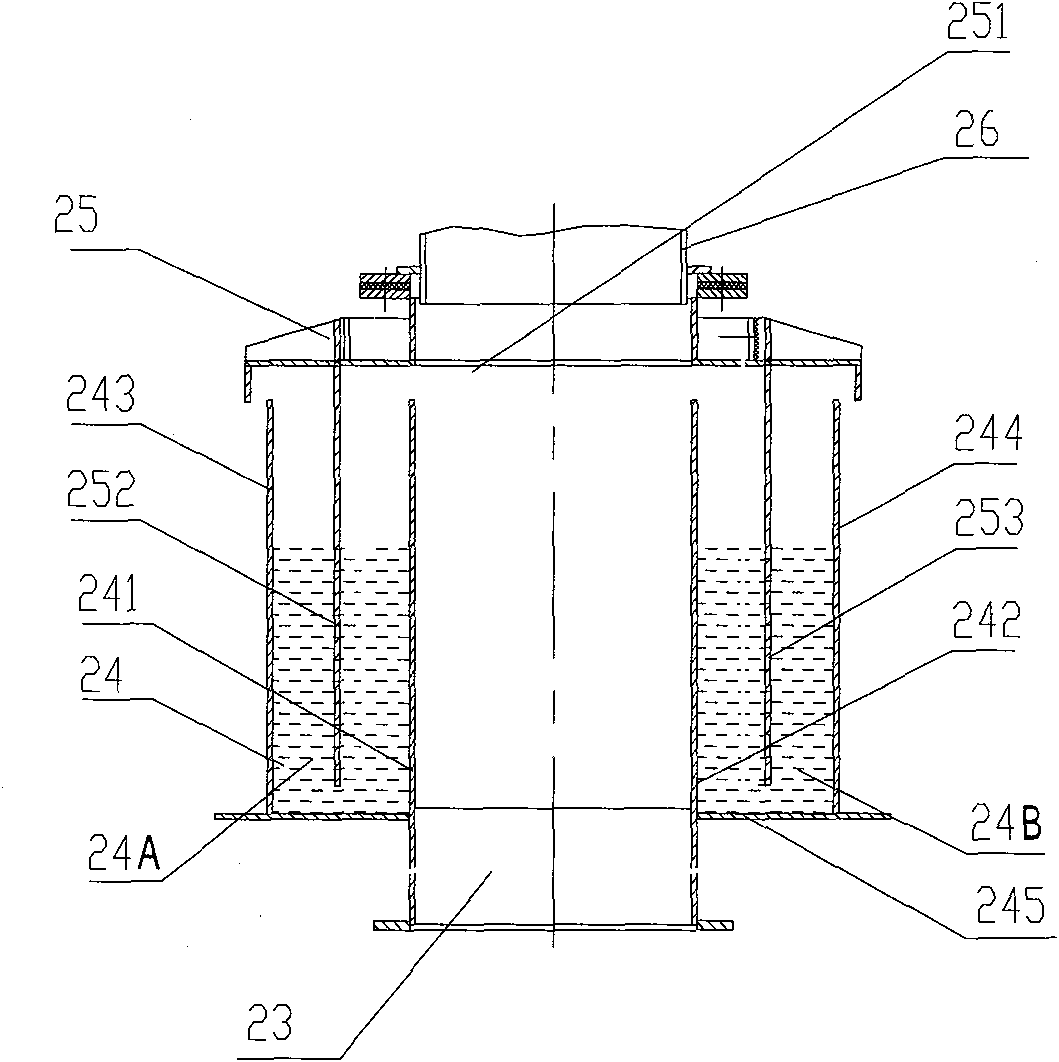
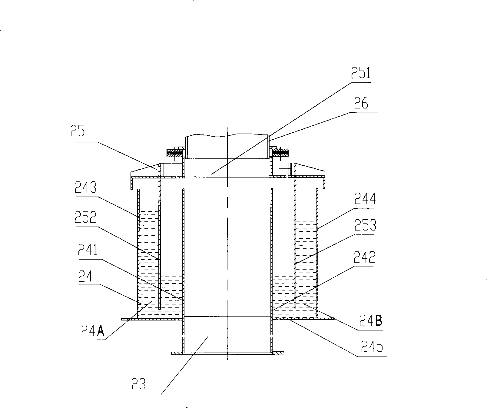
Known by Pt=mgh, this will cause the inner and outer liquid surfaces of the annular inner liquid tank 24A and the annular outer liquid tank 24B to vibrate up and down. If the vibration amplitude is too large, part of the liquid will enter the trolley (not shown in the figure) with the cold wind. Make the dust material stick on the grate plate (not shown in the figure) of the trolley, affect the ventilation of the wall plate, and also make the dust material on the lower plate (not shown in the figure) of the trolley stick on the lower plate, Affect the static seal of the trolley
Method used
View moreImage
Smart ImageViewing Examples
Examples
Embodiment Construction
Login to View More PUM
 Abstract
The invention discloses an air inlet system of an annular cooling machine. An annular air duct consists of an annular liquid groove and a door-shaped sealing device; a sealing cover plate of the door-shaped sealing device covers on the annular liquid groove; an inner annular plate and an outer annular plate of a door-shaped air duct of the door-shaped sealing device extend downwards to the below of the liquid levels of an annular inner liquid tank and an annular outer liquid tank of the annular liquid tank respectively; the distance from an inner annular plate of the door-shaped air duct to an inner side annular plate of the annular inner liquid tank is larger than the distance from the inner annular plate of the door-shaped air duct to the inner annular plate of the annular air duct of the annular inner liquid tank; and the distance from an outer annular plate of the door-shaped air duct to an outer side annular plate of the annular outer liquid tank is larger than the distance from the outer side annular plate of the annular outer liquid tank to the outer annular plate of the annular air duct. The invention also discloses the annular air duct. The air inlet system can effectively prevent liquid in the annular liquid tank from splashing by overlarge vibration amplitude and ensures normal operation of the annular cooling machine.
Description
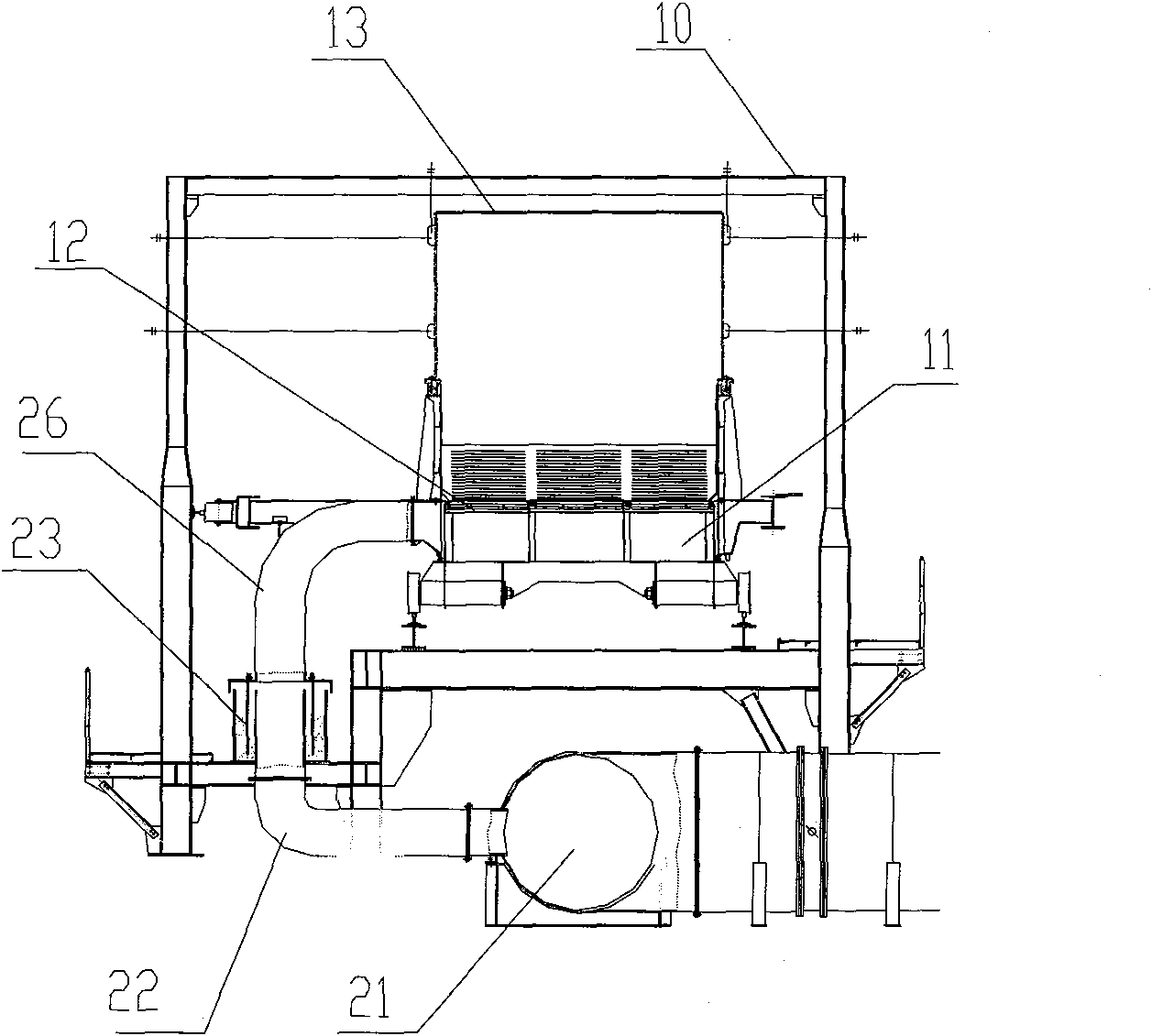
A kind of air inlet system of annular cooler and its annular air duct technical field The invention relates to the field of iron and steel smelting, in particular to an air inlet system of an annular cooler and an annular air duct thereof. Background technique In iron and steel smelting, ring coolers are used to cool sintered materials. The ring cooler is in the shape of a ring as a whole, and the sintered material runs in the ring cooler for a week through a trolley to complete cooling and unloading. Referring to Fig. 1, it is a radial (pointing to the center of the annular cooler) sectional view of the annular cooler 10, the main air duct 21 is connected to each branch air duct 22, the branch air duct 22 is connected to the annular air duct 23, and the outlet of the annular air duct 23 is connected to The trolley air inlet pipe 26 is connected to the trolley 11. The sintered materials are arranged on the grate plate 12 of the trolley 11, and the trolley 11 rotates aro...
Claims
Login to View More Application Information
Patent Timeline
 Patent Type & Authority Patents(China)
IPC IPC(8): F27D15/02
Inventor 高德亮
Owner ZHONGYE-CHANGTIAN INT ENG CO LTD
Features
- R&D
- Intellectual Property
- Life Sciences
- Materials
- Tech Scout
- Unparalleled Data Quality
- Higher Quality Content
- 60% Fewer Hallucinations
Learn More Browse by: Latest US Patents, China's latest patents, Technical Efficacy Thesaurus, Application Domain, Technology Topic, Popular Technical Reports.
© 2025 PatSnap. All rights reserved.Legal|Privacy policy|Modern Slavery Act Transparency Statement|Sitemap|About US| Contact US: help@patsnap.com


