
Clamping device

一种夹持装置、夹持的技术,应用在测量装置、夹钳、服饰等方向,能够解决工件变形、影响检测结果准确性、很难把握力度等问题

Inactive Publication Date: 2009-04-29
HONG FU JIN PRECISION IND (SHENZHEN) CO LTD +1
View PDF0 Cites 3 Cited by
  • Summary
  • Abstract
  • Description
  • Claims
  • Application Information

AI Technical Summary

Problems solved by technology

In this detection method, it is difficult to grasp the strength by holding the workpiece by hand. For workpieces with thin wall thickness, it is easy to artificially cause deformation of the workpiece and affect the accuracy of the detection results.

Method used


Image

  • Clamping device
  • Clamping device
  • Clamping device

Examples


Embodiment Construction

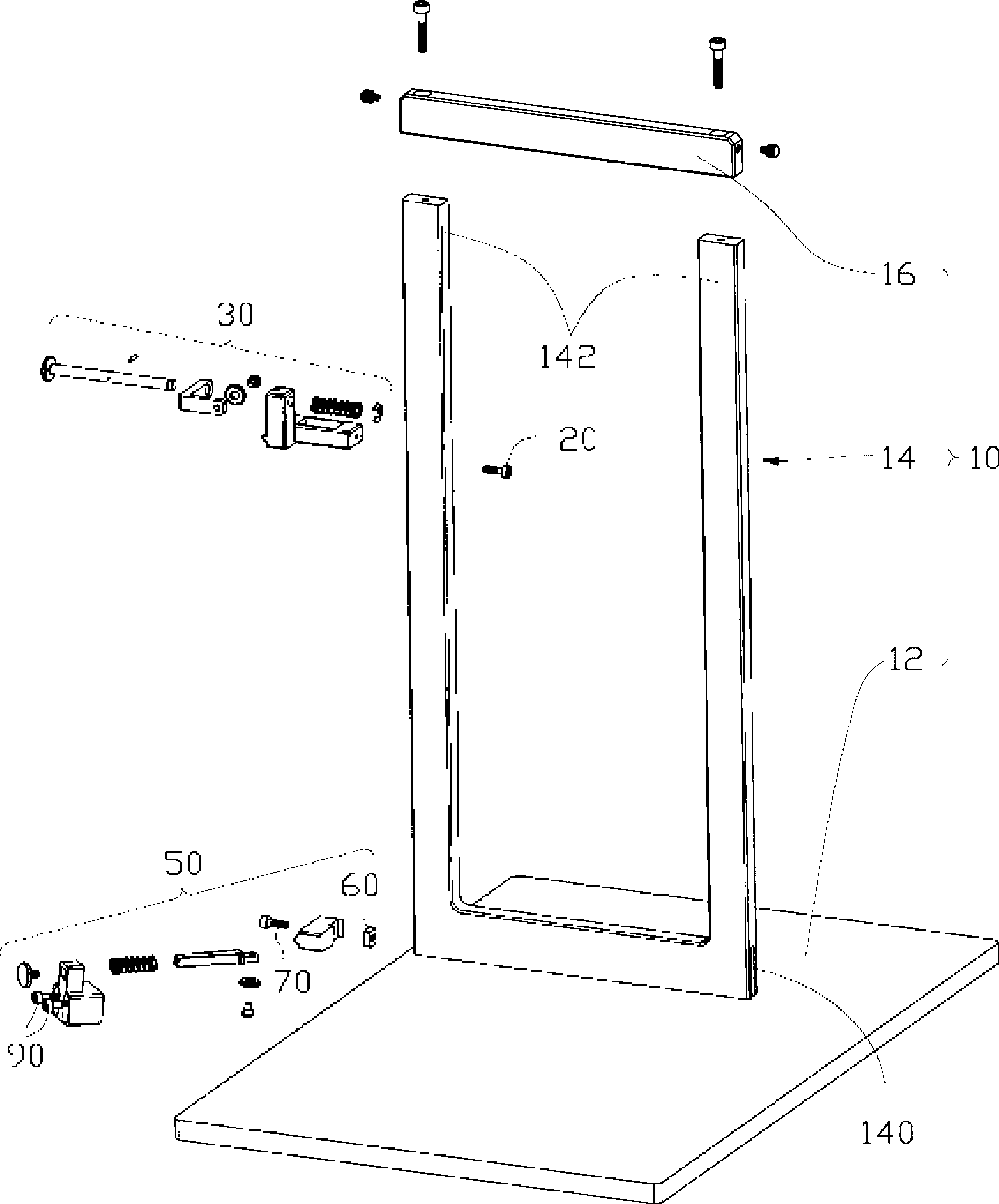
[0013] Please refer to figure 1 , a preferred embodiment of the clamping device of the present invention, which includes an operating frame 10 , a first clamping part 30 and a second clamping part 50 .

[0014] The operating frame 10 includes a platform 12 , a “U”-shaped bracket 14 vertically installed on the platform 12 and a beam 16 connecting the upper end of the bracket 14 . The bracket 14 includes two vertically parallel supporting arms 142 , and a sliding slot 140 is respectively provided on the sides of the two supporting arms 142 adjacent to the platform 12 .

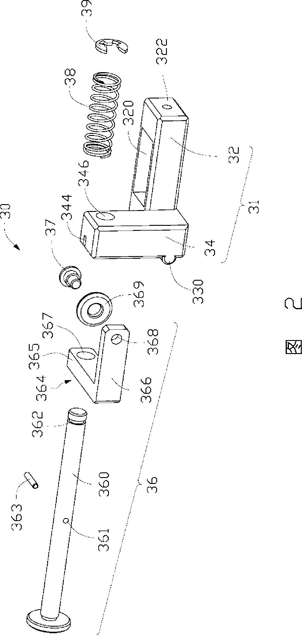
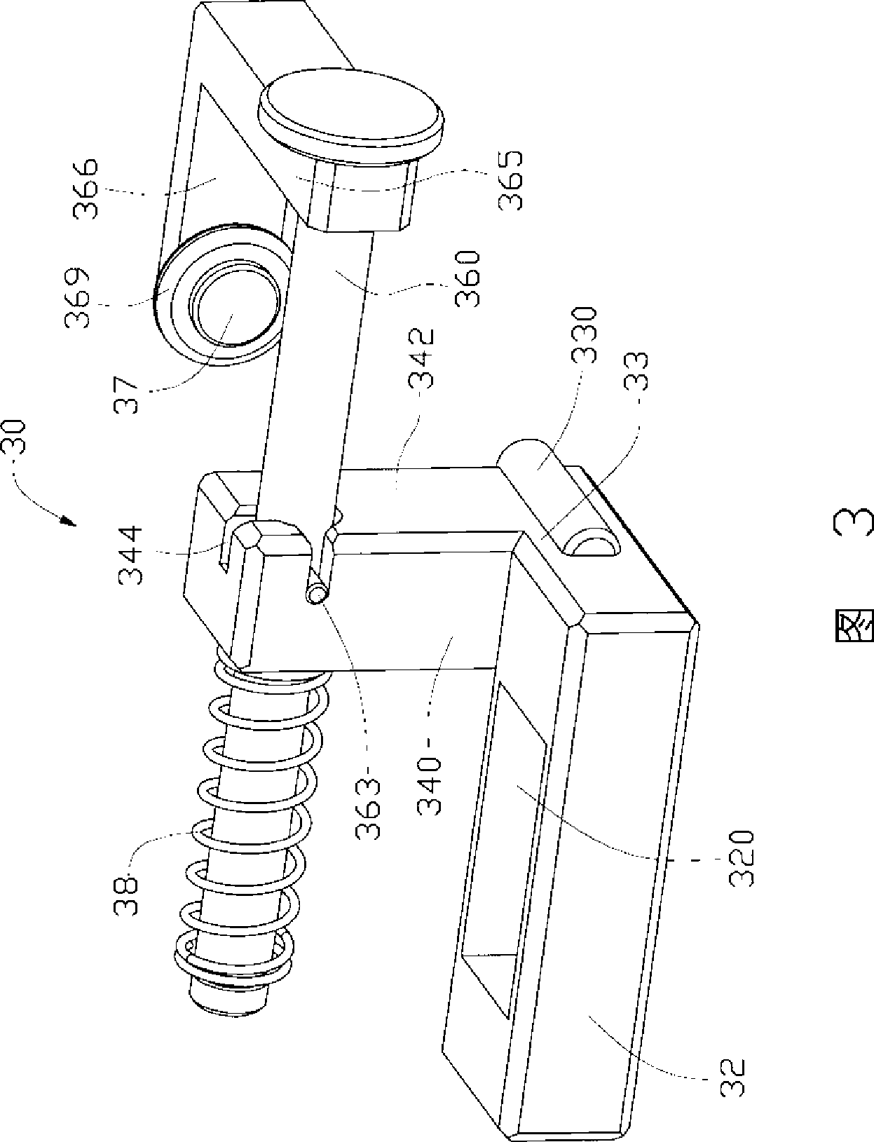
[0015] Please refer to FIG. 2 and FIG. 3 together. Please refer to FIG. 2 and FIG. 3 together. The first clamping member 30 includes a positioning member 31 , a clamping portion 36 and a spring 38 . The positioning member 31 includes a horizontal rectangular sliding portion 32 , and a vertical rectangular locking portion 34 located at one side and one end of the sliding portion 32 . A rectangular through hole ...


PUM


Abstract

The invention provides a clamping device for fixing to-be-detected plates. The clamping device comprises a platform, a bracket perpendicularly arranged on the platform, as well as a first clamping piece and a second clamping piece which are arranged on the bracket in an upper-lower way, wherein the first clamping piece comprises a clamping part capable of elastic reset and a positioning piece; the positioning piece is provided with a first positioning block; a first clamping head matched with the first positioning block is arranged on the clamping part; the second clamping piece comprises a moving part arranged on the lower part of the bracket and a pushing part which is arranged on the platform and is capable of elastic reset; a second positioning block is arranged on the moving part; and the pushing part is provided with a second clamping head capable of matching with the second positioning block. When the clamping device is used, the first positioning block is adjusted to be matched with the first clamping head and is used to clamp the upper part of a to-be-detected plate, and the second positioning block is matched with the second clamping head to clamp the lower part of the to-be-detected plate, so as to ensure that the to-be-detected plate can not have torsional deformation. The clamping device has the advantages of fast and convenient use.

Description

technical field [0001] The invention relates to a clamping device, in particular to a clamping device for fixing a plate workpiece to be tested in a detection system. Background technique [0002] In many inspection processes, how to fix the board to be tested without causing deformation of the workpiece has always puzzled us. For example, during the injection molding and baking process of the front and rear covers of a notebook computer, the degree of deformation of the plane directly affects the quality of the product, so flatness testing is particularly important. However, the existing detection method is to stand the board to be tested on one side of the jig, stick to the two positioning pins of the jig near the upper and lower edges, and support it with hands. Then the deformation value of the board to be tested is measured by the measuring system. In this detection method, it is difficult to grasp the strength by holding the workpiece by hand. For a workpiece with a ...

Claims


Application Information

Patent Timeline
Patent Type & Authority Applications(China)
IPC IPC(8): G01D11/00G01D11/16
CPCB25B5/003B25B5/145Y10T24/44641
Inventor 张秉君宫连仲
Owner HONG FU JIN PRECISION IND (SHENZHEN) CO LTD
Learn More