Method for demarcating multi line scan video cameras

A line-scanning camera and calibration method technology, which is applied in the field of multiple line-scanning camera calibration, can solve the problems of affecting the synchronization of cameras, merging of images, and the difficulty of accurate size calculation, so as to achieve the effect of improving calibration efficiency and increasing calibration accuracy

Active Publication Date: 2009-04-29
BAOSHAN IRON & STEEL CO LTD
View PDF0 Cites 28 Cited by
  • Summary
  • Abstract
  • Description
  • Claims
  • Application Information

AI Technical Summary

Problems solved by technology

This error will greatly affect the synchronization of multiple cameras, and cause di

Method used


Image

  • Method for demarcating multi line scan video cameras
  • Method for demarcating multi line scan video cameras
  • Method for demarcating multi line scan video cameras

Examples


Embodiment Construction

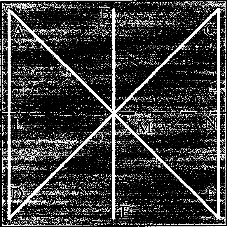
[0039] see figure 2 , the method for the calibration of multiple line scan cameras of the present invention is designed with a calibration plate 1, which is a rectangular plate, on which 8 narrow slit light sources are arranged around and diagonally, and the four corner endpoints are respectively defined as A and C , F, D, the intersection point of the diagonals is M, and the midpoints between the endpoints A, C, F, and D are B, N, E, and L respectively; so far AD, CF, AM, BM, CM, DM, and EM are formed , 8 narrow slit light sources of the FM line, LN is the horizontal reference line; the 8 light sources are controlled by independent power switches;

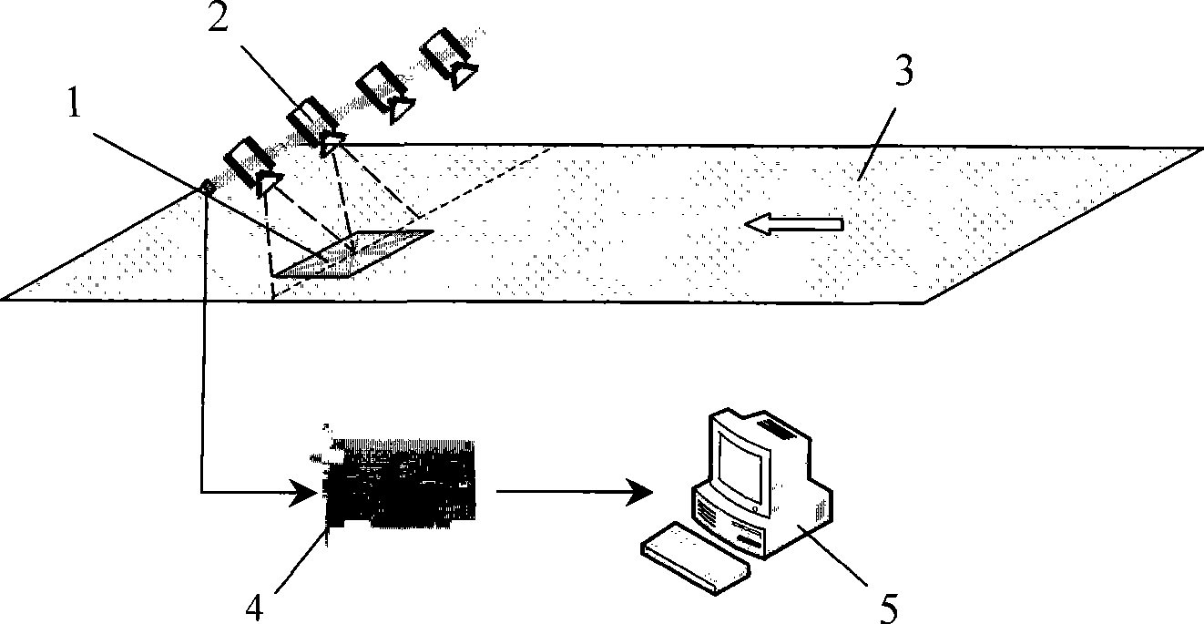
[0040] see figure 1 , the camera 2 is installed on a multi-degree-of-freedom adjustment mechanism, the installation position of the camera is basically determined, and precise positioning is required. The output of the camera 2 is stored in the computer 5 via the image acquisition card 4 .

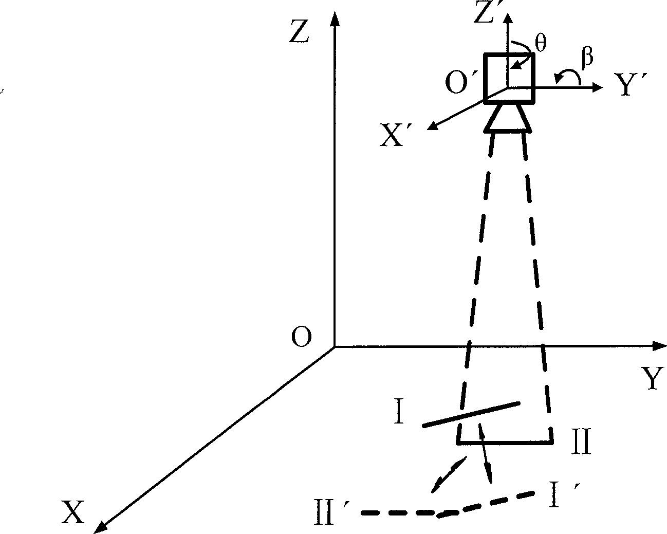
[0041]Two reference coordinate syst...


PUM


Abstract

The invention discloses a method for calibrating a plurality of line scanning cameras, which comprises the following steps: designing a rectangular calibrating plate on which 8 narrow slit light sources are arranged along the periphery and the diagonal positions; establishing a band coordinate system O-XYZ and a camera coordinate system O'-X'Y'Z'; namely, a) determining the position of the calibrating plate, making a datum line of the calibrating plate parallel to the width direction of a band, and aligning the calibrating plate to a camera; b) adjusting an imaging position of the camera to make the imaging position parallel to the Y axis in an XOY plane, and adjusting a target position II from an initial imaging position I; c) determining a superposed area between adjacent cameras, and adjusting the imaging position of the camera from position II to position III in the XOY plane; d) translating the imaging position to make the imaging position moved to a referenced collinear position IV where a plurality of cameras image; and e) repeating above steps, and calibrating the adjacent cameras until finishing calibrating n cameras. The method can conveniently and quickly debug the line scanning cameras in shorter time to make the cameras cooperatively work.

Description

technical field [0001] The invention relates to the technical field of detection, in particular to a method for calibrating multiple line scan cameras. Background technique [0002] At present, the online detection system for surface defects based on machine vision has been successfully applied to various continuous strip production lines, such as strip steel, aluminum foil, copper foil, paper, plastic and textiles, etc., which can realize real-time and efficient detection of surface defects on these strips Check out. Most of this type of inspection equipment relies on high-speed cameras to continuously take images of materials on the production line to analyze whether there are defects and what kind of defects exist. [0003] On the high-speed moving strip production line, most visual imaging systems use line scan cameras. Depending on the width of the strip to be filmed, a different number of cameras are required for side-by-side and parallel filming. In order to ensure...

Claims


Application Information

Patent Timeline
IPC IPC(8): G01N21/93
Inventor 王康健石桂芬林秀贞何永辉王健宗德祥陆丽华乔俊良
Owner BAOSHAN IRON & STEEL CO LTD
Why Eureka
Try Eureka