Production line real time acquiring and data accounting system and method

A statistical data and real-time collection technology, applied in the direction of comprehensive factory control, comprehensive factory control, electrical program control, etc., can solve problems such as increased manpower input, increased data distortion, and human statistical errors, so as to save labor costs and reduce errors , the effect of good product quality

Active Publication Date: 2009-04-29
ZTE CORP
2 Cites 43 Cited by

AI-Extracted Technical Summary

Problems solved by technology

[0006] (1) Increase data distortion
Using the method of manual statistical data, there is a probability of human statistical error, and the collected data may not truly reflect the real situation of the production line
[0007] (2) Increased manpower input
Using the method of manual statistics requires personnel to collect and enter the data of the production line. When the production scale is large, the input of manpower is very large, which increases the cost of production
[0008] (3) Difficulty in product classification and statistics
Therefore, if manual statistical m...

Method used

[0054] The distributed control machine 102 is also responsible for the control of data classification storage and production tempo. In the production process, the production efficiency of the production line has a great correlation with the production beat. The production takt depends on two factors: the coordination of the production capacity of each process and the qualified rate of the produced products. If the production capacity of each process is inconsistent, according to the short board principle, the overall production efficiency is equal to the process with the lowest production capacity. Through the analysis of real-time data by the distributed control machine 102, the production capacity of each production process can be effectively adjusted, and the tempo of each process can be coordinated to achieve the optimal effect. When the qualification rate of the produced products is too low, the produced products will cause the quality of the production to deteriorate. This situation may be due to a problem in a certain component or a certain production link. Through the fault classification and real-time display function of the distributed control machine 102, the management personnel on the production site can correct the fault in time to ensure the quality of the produced products.
[0056] The distributed control machine 102 converts the production information into the storage format of the standard da...

Abstract

The invention relates to a system used for real-time data collecting and counting on a production line. The system comprises a concentrated server, a distributed controller, a data collector and a data collecting terminal. The concentrated server is connected with the distributed controller, so as to realize storage, analysis, counting and report generation for various production condition data on the production line, thereby providing data support for dispatching and collocating of production; the distributed controller is connected with the data collector to collect data in the data collector real-time, so as to analyzing and counting the data primarily, thereby periodically storing operation results into the concentrated server and searching required production information from the concentrated server; the data collector is connected with the data collecting terminal, so as to separate, rectify, read and store electrical signals transmitted from the data collecting terminal and transmit the data to the distributed controller in real time; and the data collecting terminal is used for converting on-spot production information into electrical signals and then transmitting the electrical signals to the data collector. The system provides possibilities to control cycle time in real time and obtain excellent product quality.

Application Domain

Technology Topic

Image

  • Production line real time acquiring and data accounting system and method
  • Production line real time acquiring and data accounting system and method
  • Production line real time acquiring and data accounting system and method

Examples

  • Experimental program(1)

Example Embodiment

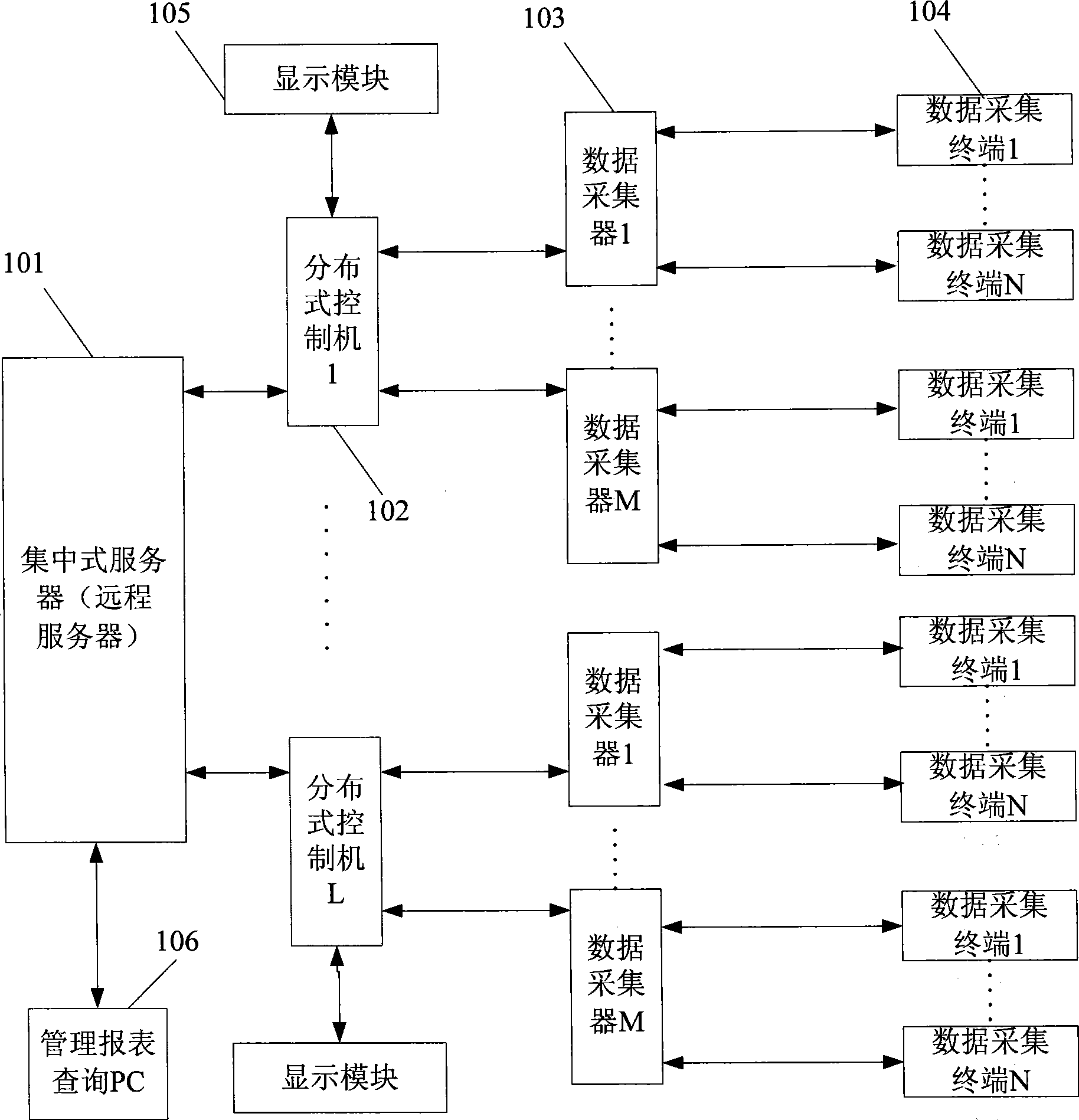
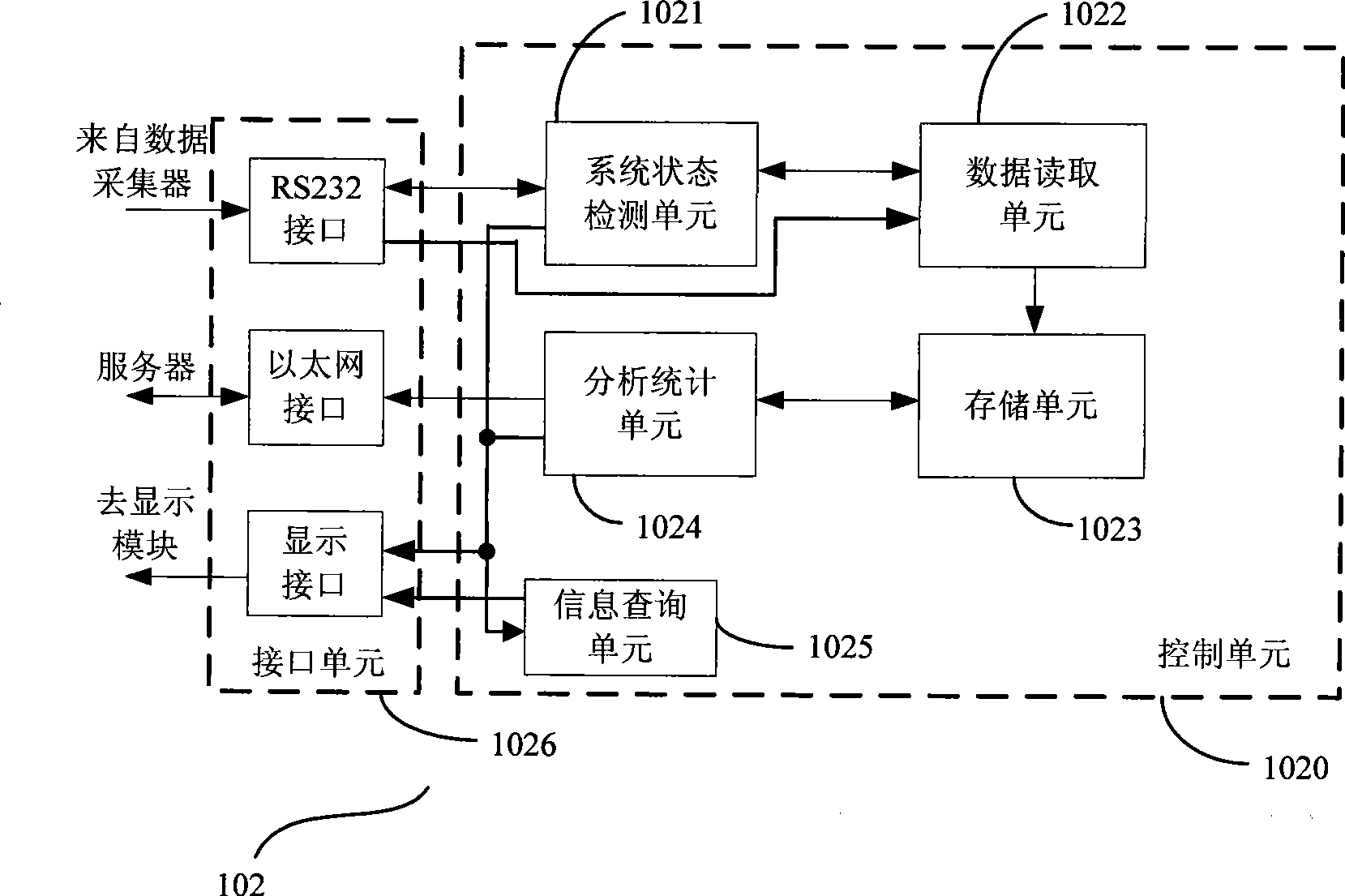
[0042] The system and method for real-time collection and statistical data of the production line of the present invention converts all kinds of information produced into digital level, pulse and other signals through one or more data collection terminals, and the data collector collects, stores and timely Reported to the distributed control machine; after the distributed control machine reads the production information from multiple data collectors of one or more production lines for statistics and analysis, it displays some key production data on the display in real time On the terminal, to guide the production line managers to adjust the production rhythm in time; at the same time, the collected, statistical and analyzed data are regularly reported to the centralized server through the Ethernet interface; the centralized server performs multiple distributions from many pipelines The production information in the integrated control machine is stored and the production report is generated; the production line manager can inquire various production reports stored in the centralized server on the management report query PC through the transmission of Ethernet, as its real-time adjustment of the production beat And an important basis for controlling product quality.
[0043] The above technical solutions of the present invention will be described in detail below in conjunction with embodiments and drawings.
[0044] Such as figure 1 Shown is the structural block diagram of the system for real-time collection and statistical data of the production line of the present invention. The system includes: a centralized server (such as a remote server) 101, one or more distributed control machines 102, and one or more data collectors 103 , Multiple data collection terminals 104, display module 105, and report query terminal 106. among them:
[0045] The centralized server 101 can be a remote server. As the database of the entire system, it can be connected to many distributed control machines 102. It is mainly responsible for the storage, analysis, statistics and report generation of various production situation data of the production line, and provides for production scheduling and deployment. Data support.
[0046] The multi-distributed control machine 102 is the main control part of the system execution. Its external interfaces mainly include: an Ethernet interface for communication with a centralized server, an RS232 interface for communication with a data collector, and an interface with a display module.
[0047] The multi-distributed control machine 102 is generally borne by a PC (it can also be borne by a network computer NC or an embedded control system). It is connected with one or more data collectors 103 to collect the data in the data collector 103 in real time. After preliminary analysis and statistics, it is displayed on the display module 105, and the production information is regularly stored in the database of the centralized server 101. As the main control system for data collection in a small area, it is mainly used to achieve:
[0048] (1) Control data collection
[0049] Control the data collection of the data collector 103, read the data in the data collector 103 in real time, query the running status of the data collector 103 and its network connection status, so that the production data collection system in a small area is in a normal running state . When it inquires that the data collector 103 itself is faulty or its communication part is faulty, it starts the exception handling process to try to repair the fault of the data collector 103 or the communication network failure; when the fault cannot be repaired, the distributed control machine 102 will Send an alarm signal to the management staff at the production site to notify the management staff to detect system equipment.
[0050] (2) Collect, store and query production data in a small area
[0051] As a data acquisition control system in a small area, the distributed control machine 102 needs to control the data collector 103 to collect all the production information in the small area, and realize a certain capacity of real-time storage of the collected data for short time Data analysis and display, so that on-site managers can query the historical production information of the production line.
[0052] (3) Analyze and display production data in a small area
[0053] The distributed control machine 102 is also connected with the display module 105 to perform preliminary analysis on the data stored in real time, and display key data that affect the production quality and production cycle on the display module 105 in real time. By referring to these key production data, the production site manager decides whether it is necessary to coordinate the production tempo or check the related production process and equipment.
[0054] The distributed control machine 102 is also responsible for the control of data classification and storage and production rhythm. In the production process, the production efficiency of the production line has a great correlation with the production cycle. The production cycle depends on two factors: the coordination of the production capacity of each process and the qualified rate of the produced product. If the production capacity of each process is inconsistent, according to the short board principle, the total production efficiency is equal to the process with the lowest production capacity. Through the analysis of real-time data by the distributed control machine 102, the production capacity of each production process can be effectively adjusted, so that the beats of each process are coordinated and the optimal effect is achieved. When the pass rate of the produced product is too low, the produced product will cause the quality of the production to deteriorate. This situation may be caused by a problem in a certain component or a certain production link. The fault classification and real-time display function of the distributed control machine 102 can enable the production site management personnel to correct the fault in time and ensure the quality of the produced product.
[0055] (4) Access data to the database of the centralized server 101
[0056] The distributed control machine 102 converts the production information into a storage format of a standard database with the centralized server 101, and transmits it to the centralized server 101 to achieve permanent storage of production data. At the same time, the 102 distributed control machine can also query the history records of all production information by accessing the centralized server 101.
[0057] The data collector 103 is connected to one or more data collection terminals, and is used to collect data from various types of data collection terminals 104, and isolate, reshape, read and read the electrical signals transmitted from the data collection terminals 104. The data is stored and transmitted to the distributed control machine 102 via the network in real time.
[0058] The data collection terminal 104 may have a variety of models, and is used to convert the production information on site into digital electrical signals such as levels and pulses, and transmit them to the data collector 103.
[0059] The display module 105 is used to display the key production information in its jurisdiction in real time under the control of the distributed control machine 102, so that the production site management personnel can understand it in time, and adjust the production rhythm accordingly; Take timely measures in case of abnormal production.
[0060] The management report query PC 106 is connected to the centralized server 101 for querying and printing all historical records of production information stored in the centralized server.
[0061] The control procedure of the distributed control machine in the system of the present invention mainly includes: a power-on initialization procedure and an information processing procedure. among them:
[0062] Power-on initialization process: After the distributed control machine is powered on, the PC system is initialized first, and then the data acquisition system client software is started to start the initialization of the production line real-time classification data acquisition system:
[0063] First, scan and initialize the connected data collector to make sure that the data collector connected to the distributed control machine is in a normal working state;
[0064] Then try to connect to the remote server to determine whether the remote server can provide data storage services;
[0065] Finally, power on to initialize the display module and display the key production data.
[0066] Information processing flow: After the above initialization work is completed, the data collector is scanned every two seconds by default, and the data representing the production information is read from the data collector;
[0067] After format conversion and analysis of the read data, the production information is displayed in real time through the display module;
[0068] When a data collector is in an abnormal working state, it will try to repair the fault many times; when the fault cannot be solved, it will issue a fault alarm to the on-site management personnel;
[0069] Write production information to the remote server within a certain period of time to achieve permanent storage of the production information; or, read the production information from the remote server and display it.
[0070] figure 2 It is the data acquisition control flow chart of the above-mentioned distributed control machine of the present invention. The main steps are as follows:
[0071] 201: The system is powered on and initialized. After the distributed control machine is powered on, the PC system is initialized first, and then the data acquisition system client software is started to initialize the real-time classification data acquisition system of the production line;
[0072] 202: Initialization of the data collector. First scan and initialize the connected data collector to make sure that the connected data collector is in normal working condition;
[0073] 203: Initialization of the remote server. Try to connect to the remote server to determine whether the remote server can provide data storage services;
[0074] 204: Initialization of the display module. Power-on and initialize the display module, and display key production data on the display module;
[0075] 205: Query whether the scan time of the data collector is reached;
[0076] 206: When the scan time of the data collector set by the customer arrives, read the production information from the data collector;
[0077] 207: Determine whether the data in the data collector can be successfully read;
[0078] 208: When it is judged that the data can be read from the data collector normally, perform step 210; and when it is judged that a certain data collector is in an abnormal working state, it will try to repair the fault many times;
[0079] For example, first try to re-read the data multiple times. If the data still fails to be read normally, then check whether the connection with the data collector is faulty, and try to re-drive multiple times to determine whether the fault can be eliminated ;
[0080] 209: When it is determined that the fault has been eliminated, perform step 210; and when it is determined that the fault cannot be eliminated, issue a fault alarm to the on-site management personnel;
[0081] 210: Update the real-time data on the display module. Read the production information from the data collector for format conversion and analysis, and then display it in real time through the display module;
[0082] 211: Determine whether the update time of the remote server has arrived;
[0083] 212: When the update time of the remote server set by the customer arrives, write production information to it to achieve permanent storage of the production information; and when the update time has not arrived, return to step 205.
[0084]Of course, in this process, you can also search for the required production information and display it by accessing the remote server; or, search for the history of all production information and print it.
[0085] image 3 It is the principle block diagram of the distributed control machine 1 in the system for real-time collection and statistical data of the production line of the present invention. The distributed control machine 102 includes two parts: a control unit 1020 and an interface unit 1026, which are respectively used to control the data collection of the system and The data collector, centralized server and display module communicate. The control unit 1020 includes a system state detection unit 1021, a data reading unit 1022, a storage unit 1023, and an analysis and statistics unit 1024 connected in sequence, and an information query unit 1025; among them:
[0086] The system status detection unit 1021 is connected to the RS232 interface in the interface unit 1026, and is used to initialize the data collector 103, and periodically query the running status and connection status of the data collector 103, so that the production data in the small area under its jurisdiction The acquisition system is in a normal operating state; after the data reading unit 1022 fails to read data, restart its data reading, and check the network connection status between the data reading unit 1022 and the data collector, and try to drive the network connection again. To try to eliminate the data collection failure; when it is confirmed that the failure cannot be eliminated, perform system alarm operations on the display module 105 through the display interface in the interface unit 1026, such as sound, light or other forms of alarm;
[0087] The data reading unit 1022, which is also connected to the RS232 interface in the interface unit 1026, is used to store the real-time read data in the data collector 103 in the storage unit 1023; through the Ethernet interface in the interface unit 1026, timing Report the read data to the centralized server 101, and update the display data on the display module 105 in real time through the display interface in the interface unit 1026;
[0088] The storage unit 1023 is configured to store the data read by the data reading unit 1022, and store the analysis and statistical data of the analysis and statistics unit;
[0089] The analysis and statistics unit 1024 is used to analyze and count the real-time data stored in the storage unit and store it in the storage unit 1023; through the Ethernet interface in the interface unit 1026, periodically report the analysis and statistics results to the centralized server 101; And through the display interface in the interface unit 1026, update the analysis and statistical data on the display terminal 105;
[0090] The information query unit 1025 is respectively connected to the Ethernet interface and the display interface in the interface unit 1026, and is used to display the searched production information on the display module 105 by accessing the centralized server 101.
[0091] Figure 4 It is the principle block diagram of the data collector in the system for real-time collection and statistical data of the production line of the present invention. The data collector 103 includes a communication module 1031, a control system 1032, a processing and storage unit 1033, and a signal isolation unit 1034 connected in sequence. among them:
[0092] The communication module 1031 is used to provide communication control and physical links for data interaction with the distributed control machine 102.
[0093] The control system 1032 is used for realizing the overall system control of the data collector 103, that is, realizing data acquisition and communication functions.
[0094] The processing and storage unit 1033 is used for storing various electrical signals transmitted from the data collection terminal 104 after dithering, shaping, and reading, and then storing them in a corresponding storage unit for reading by the distributed control machine 102.
[0095] The signal isolation unit 1034 is used to isolate various interference signals from the production line to prevent damage to the data collector 103.
[0096] The system and method for real-time data collection on the production line of the present invention converts various production information into digital signals and collects, analyzes, and counts them automatically and in real time, saving labor costs and reducing human errors. Since it can provide real-time production status reports for the production phenomenon management personnel, it provides a basis for the coordination of various processes and also provides the possibility for real-time control of the production site beat. Moreover, the present invention is easy to classify and count the products on the assembly line, and thus can analyze the production status of various types of products customized by customers, so as to obtain good product quality. The present invention defines each device and each module in the system for this purpose. But it is not limited to these devices and these modules.
[0097] Although the preferred embodiments of the present invention have been disclosed as above, they are not intended to limit the present invention. Anyone familiar with the art can make some changes and modifications without departing from the spirit and scope of the present invention. The protection scope of the invention shall be defined by the foregoing claims.

PUM

no PUM

Description & Claims & Application Information

We can also present the details of the Description, Claims and Application information to help users get a comprehensive understanding of the technical details of the patent, such as background art, summary of invention, brief description of drawings, description of embodiments, and other original content. On the other hand, users can also determine the specific scope of protection of the technology through the list of claims; as well as understand the changes in the life cycle of the technology with the presentation of the patent timeline. Login to view more.

Similar technology patents

Method and system for automatically conveying packages, robot and storage device

ActiveCN108401423AReduce human-involved componentsReduce labor costsSortingEngineeringRobot
Owner:SHENZHEN DORABOT ROBOTICS CO LTD

Classification and recommendation of technical efficacy words

  • Reduce labor costs
  • Reduce mistakes

Thin-skin ultralight recreational vehicle body system

InactiveUS7000978B1Elimination of bonding processReduce labor costsVehicle seatsSuperstructure subunitsExtremely lightVehicle frame
Owner:MESSANO FR

Terminal positioning track fitting method based on Bezier curve

ActiveCN102998684AReduce mistakesSatellite radio beaconingSatellite navigationFitting methods
Owner:XIAMEN YAXON NETWORKS CO LTD

Multifunctional road soil roadbed freezing and thawing circulating test device

ActiveCN101923085ASolving Elasticity ProblemsReduce mistakesRoadwaysEarth material testingTest measurementFrost
Owner:CCCC SECOND HIGHWAY CONSULTANTS CO LTD
Why Eureka
Try Eureka